Brush cutter

A technology of brush cutters and cutting lines, applied in the direction of harvesters, cutters, agricultural machinery and implements, etc.

Inactive Publication Date: 2013-02-06
MAKITA CORP
View PDF9 Cites 8 Cited by
  • Summary
  • Abstract
  • Description
  • Claims
  • Application Information

AI Technical Summary

Problems solved by technology

However, since the reflective wall is provided outside the upper cover, it is expected that the cut piece of the cutting line will be reflected in an unexpected direction.

Method used


Image

  • Brush cutter
  • Brush cutter
  • Brush cutter

Examples


Embodiment Construction

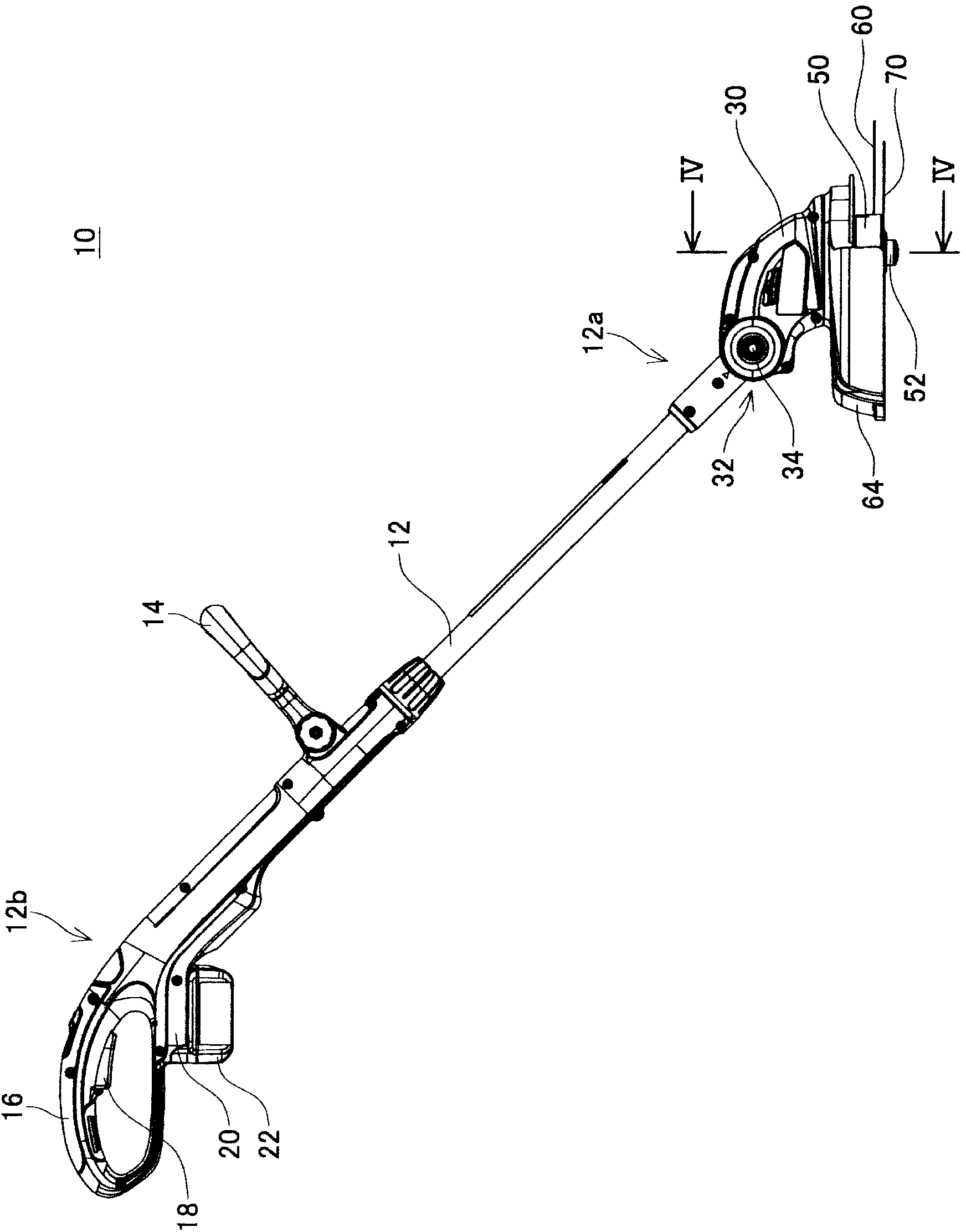
[0022] The brush cutter 10 of the embodiment will be described with reference to the drawings. The brush cutter 10 is a power tool for gardening and is used for trimming vegetation. Such as figure 1 As shown, the brush cutter 10 includes a joystick 12 . A handle 14 and a grip 16 are provided at the rear end 12 b of the operating lever 12 . Normally, the user uses the brush cutter 10 by holding the handle 14 and the grip 16 respectively. A trigger switch 18 as an activation switch is provided on the grip portion 16 . In addition, below the grip portion 16, a battery mounting portion 20 that detachably accommodates a battery pack 22 is provided. The brush cutter 10 of this embodiment is a cordless brush cutter using a rechargeable battery pack 22 as a power source.

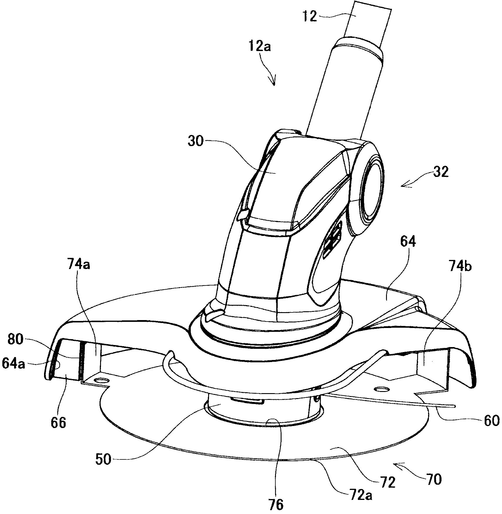
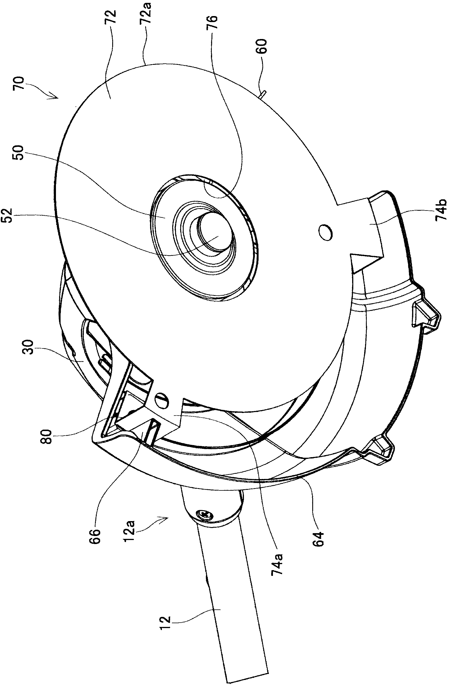
[0023] Such as figure 1 , figure 2 and image 3 As shown, a motor housing 30 is provided at the front end 12 a of the operating lever 12 . The motor housing 30 is formed of a resin material. The motor hou...


PUM


Abstract

The invention provides a brush cutter used for preventing cutting blades of the cutting line from flying towards the user. The brush cutter (10) comprises an operating rod (12) and a cord holder (50) configured to be rotatably driven at a front end (12a) of the operating rod (12). A cutting cord (60) is held by the cord holder (50) and configured that a tip of the cutting cord (60) is drawn out from the cord holder (50). The brush cutter (10) further comprises an upper cover (64), a trimming cutter (80) and a bouncing wall (66). The upper cover (64) is configured to cover from an upper side and lateral side a part of region in which the cutting cord (60) extending from the cord holder (50) revolves. The trimming cutter (80) is configured to cut the tip of the cutting cord (60) drawn out from the cord holder (50). The bouncing wall (66) is located inside the upper cover (64) and configured to bounce off a cut piece of the cutting cord (60) cut by the trimming cutter (80) toward an opposite side from a user. In the brush cuter (10), the bouncing wall (66) is arranged at inner side of the upper cover.

Description

technical field [0001] The present invention relates to a brush cutter for trimming vegetation, in particular to a wire-type brush cutter using a rope-shaped cutting wire as a cutting knife. Background technique [0002] Patent Document 1 discloses a wire-type brush cutter. The brush cutter includes: an operating lever; a wire holder driven to rotate at the front end of the operating rod; a cutting wire held by the wire holder; an upper cover covering the slave wire from above and sideways. At least a part of the range in which the cutting wire protrudes from the holder; a wire sending button which is provided on the wire holder and which is pressed to send out the cutting wire; a trim cutter for cutting The top end of the cutting wire sent out from the wire holder; and the reflective wall for reflecting the cut piece of the cutting wire cut by the trimming knife toward the side opposite to the user. [0003] Patent Document 1: Specification of US Patent No. 4,651,422 [...

Claims


Application Information

Patent Timeline
Patent Type & Authority Applications(China)
IPC IPC(8): A01D34/416
CPCA01D34/4167A01D75/206A01D34/90A01D34/416
Inventor 大野彰子
Owner MAKITA CORP
Why Eureka
Try Eureka