Electric cutting system

a cutting system and electric technology, applied in the field of electric cutting systems, can solve the problems of limited effectiveness, high vibration of rotating tools, and low output power, and achieve the effects of small and less expensive components, sufficient output power, and reduced vibration levels

Active Publication Date: 2015-06-04
HUSQVARNA AB
View PDF28 Cites 25 Cited by
  • Summary
  • Abstract
  • Description
  • Claims
  • Application Information

AI Technical Summary

Benefits of technology

[0012]It is an object of the present invention to provide a power supply device, that may provide sufficient output power with smaller and less expensive components than those disclosed in the prior art.

Problems solved by technology

This results in that a lot of vibrations from the rotating tool and possibly the motor reach the handles and the operator.
This does reduce vibration levels to a certain degree, but has a limited effectiveness.

Method used


Image

  • Electric cutting system
  • Electric cutting system
  • Electric cutting system

Examples


Embodiment Construction

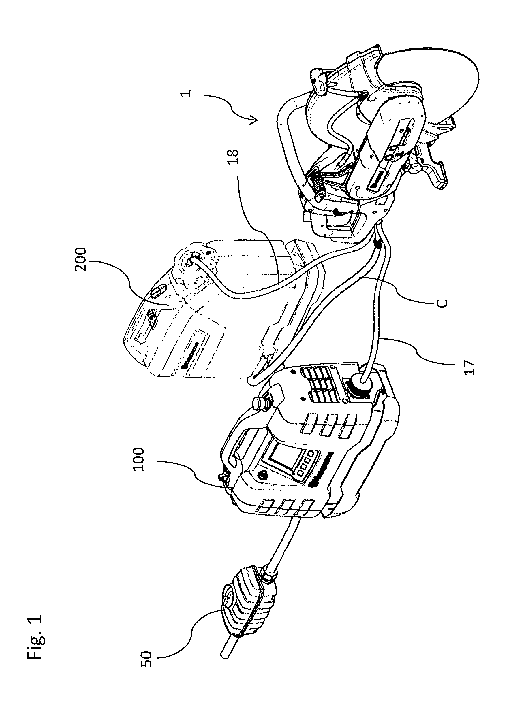
[0040]FIG. 1 shows an electric tool in the form of an electric power cutter 1, an electric power supply device 100, and a fluid source 200 in the form a water tank. The electric power supply device 100 supplies power through a cable 17 to the electric power cutter 1. It may also send data and receive feedback data from the electric cutter 1 via the cable 17. The electric power supply device 100 connects to a power grid or a generator via a residual current device 50. The electric power supply device 100 is described in more detail in relation to FIGS. 12-19. Cooling liquid, preferably cooling water, is fed from the fluid source 200 to the electric power cutter 1 through hose 18.

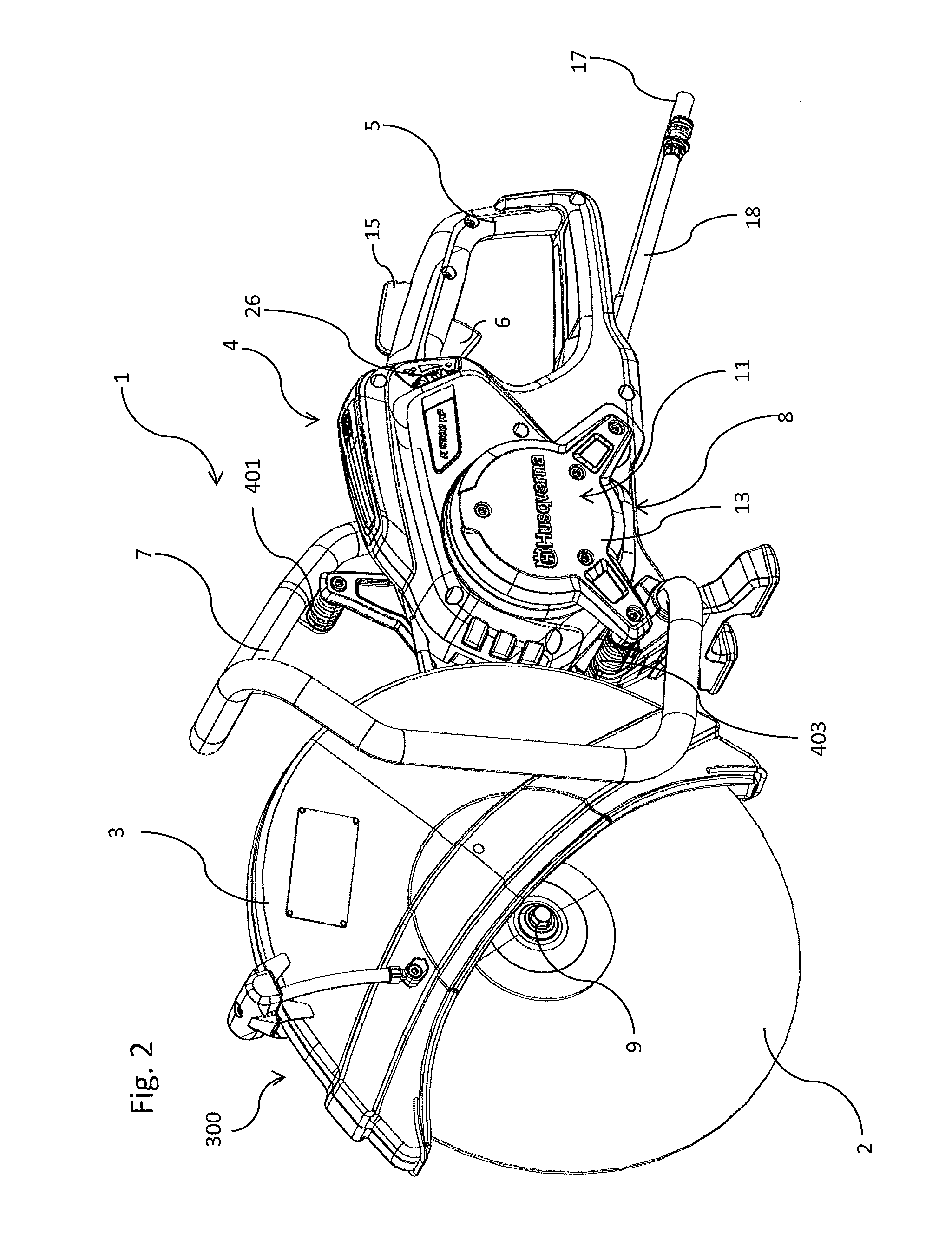
[0041]The fluid source 200 is preferably a water tank with a low pressure pump, i.e. having a feeding pressure below 3 bar, preferably below 2 bar, feeding cooling water to the motor 11 (see e.g. FIGS. 2-5) of the electric power cutter 1 through hose 18.

[0042]A return conduit C may be connected to the motor 1...


PUM

PropertyMeasurementUnit
pressureaaaaaaaaaa
pressureaaaaaaaaaa
frequencyaaaaaaaaaa

Abstract

An electric power saw/cutter (1) comprising: a. a rotatable saw structure (2) b. a rear handle (5) with a switch/speed control (6) c. a front handle (7) d. a drive unit (8) for rotating the saw structure (2), the drive unit (8) itself comprising: e. a saw structure drive arrangement (9) to which the saw structure is attachable f. a transmission (10) for driving the saw drive arrangement (9) g. an electric motor (11) for driving an input shaft (12) of the transmission h. a support structure (13) for holding/carrying the saw structure drive arrangement (9), the transmission (10) and the electric motor (11), characterised in, that the front handle (7) and the rear handle (5) are directly connected to each other to form a handle unit (4), which unit is resiliently connected to the drive unit (8), so that vibrations from the saw blade (2) and drive unit (8) will be reduced in the handle unit (4).

Description

TECHNICAL FIELD[0001]The invention is related an electric machine system and in particular an electric cutting system at least comprising an electric power cutter which power cutter comprises a rotatable circular saw blade with a protective cover, a rear handle with a switch / speed control and a front handle, a drive unit for rotating the saw blade, the drive unit itself comprising a saw blade drive shaft to which the saw blade is attachable, a transmission for driving the saw blade drive shaft, an electric motor for driving an input shaft of the transmission and a support structure for holding / carrying the saw blade drive shaft.BACKGROUND ART[0002]Electric power cutters normally have a front and a rear handle each firmly attached to a drive unit including an electric motor. This results in that a lot of vibrations from the rotating tool and possibly the motor reach the handles and the operator. In many countries daily operating times are reduced by regulations according to the measu...

Claims


Application Information

Patent Timeline
Patent Type & Authority Applications(United States)
IPC IPC(8): B27B17/00H02P6/14B23Q11/10H02K7/14H02K1/2706
CPCB27B17/00B23Q11/10H02P6/14H02K7/145B23D47/12B23D59/02B28D7/02B27B17/0033B25F5/006B25F5/008Y10T83/293B23D47/005B24B7/18B27B17/08H02K5/203H02K9/19B23B45/02B23D45/16B23D57/0015H02K1/2706H02K7/14H02P27/06
Inventor PETERSSON, ULFBERGVALL, BENGT ALLANPINZANI, HAKANCARLSSON, PARVIDLUND, ADAMBERG, JOHANBENNEHAG, ANDERS
Owner HUSQVARNA AB
Why Eureka
Try Eureka