Automatic steel bar cutting device

An automatic cutting device and steel bar technology, applied in metal processing, metal processing equipment, manufacturing tools, etc., can solve the problems of iron filings threatening human health, etc., and achieve the effects of high sawing efficiency, reduced error, and convenient operation

Active Publication Date: 2015-12-16
STATE GRID SHANDONG SHANGHE POWER SUPPLY +1
View PDF5 Cites 24 Cited by
  • Summary
  • Abstract
  • Description
  • Claims
  • Application Information

AI Technical Summary

Problems solved by technology

In addition, a large amount of iron filings will be produced during sawing, which poses a certain threat to human health

Method used


Image

  • Automatic steel bar cutting device
  • Automatic steel bar cutting device
  • Automatic steel bar cutting device

Examples


Embodiment Construction

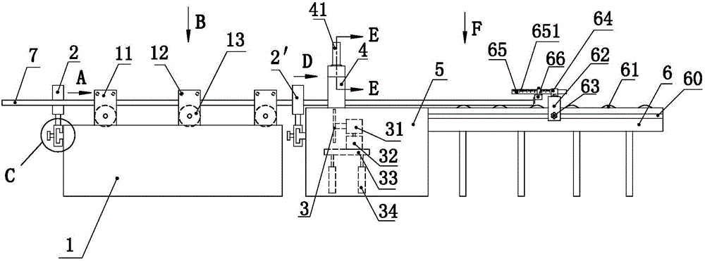
[0032] Such as Figure 1 to Figure 11 As shown, the present invention includes a conveying assembly, a cutting assembly, a clamping assembly, a guiding assembly and a measuring assembly, and the present invention will be described below in conjunction with the accompanying drawings.

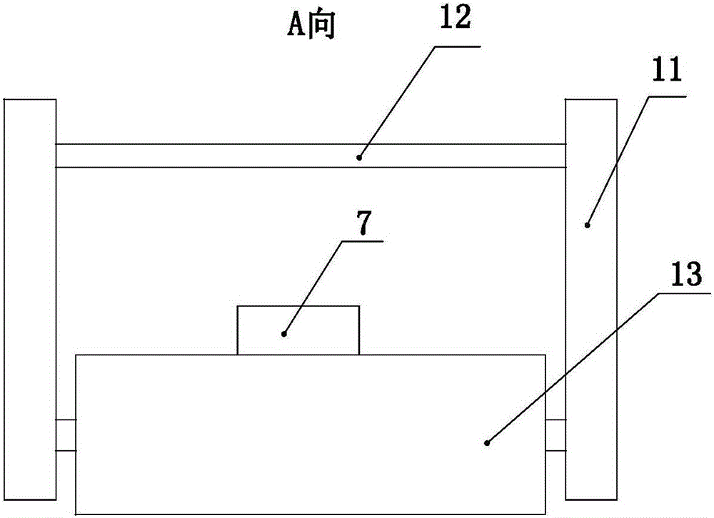
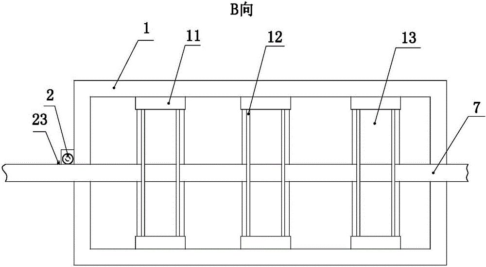
[0033] Such as Figure 1 to Figure 3 As shown, the conveying assembly includes a first support 1, a vertical plate 11, a connecting rod 12 and a conveying roller 13. The first support is a metal part of a frame structure, and legs are provided at the bottom of the first support. Several groups of vertical plates 11 are arranged on the top of the first support, and each group of vertical plates includes two vertical plates oppositely arranged, and the vertical plates are rectangular metal parts welded and fixed on the inside of the first support. The tops of the two vertical plates arranged oppositely in each group are fixedly connected by two connecting rods 12 arranged in parallel, the connecti...


PUM


Abstract

The invention relates to the technical field of steel bar cutting, in particular to an automatic steel bar cutting device used for reducing the error generated during steel bar cutting. The automatic steel bar cutting device comprises a conveying assembly, a clamping assembly, a guiding assembly, a cutting assembly and a measuring assembly. The conveying assembly mainly comprises a first support and conveying rollers, and the multiple conveying rollers are connected with a stepping motor through a transmission mechanism, wherein the stepping motor is arranged on the first support. A second support is arranged on one side of the first support, two vertical first air cylinders are fixedly installed at the bottom of the second support, and a tray is fixedly installed at the free ends of piston rods of the two first air cylinders. A motor is fixedly installed on the tray, and the output end of the motor is connected with a cutting saw through a speed reducer. A fixing frame of a gantry structure is arranged over the cutting saw, and blocking curtains are fixedly arranged at the two ends of the fixing frame respectively. A third support is arranged on one side of the second support, and the measuring assembly is arranged on the third support. The automatic steel bar cutting device is easy to operate, accurate in positioning and high in saw cutting efficiency, and the work efficiency can be greatly improved.

Description

technical field [0001] The invention relates to the technical field of steel bar cutting for electric power, in particular to an automatic steel bar cutting device. Background technique [0002] In mechanical processing, the cutting method of the existing steel bar is sawing and cutting. When it is necessary to obtain a certain length of steel bar, it is necessary to measure the steel bar with a tape measure, and then hold down the steel bar to start the cutting saw to complete the sawing operation. In this way, when the sawing length is constant, the steel bar needs to be measured every time. Because there is an error in the measurement itself, the length of the steel bar obtained by sawing is slightly different. In addition, a large amount of iron filings will be produced during sawing, which poses a certain threat to human health. Contents of the invention [0003] The purpose of the present invention is to provide an automatic cutting device for steel bars, which is u...

Claims


Application Information

Patent Timeline
Patent Type & Authority Applications(China)
IPC IPC(8): B21F11/00B21F23/00B21C51/00
CPCB21C51/00B21F11/00B21F23/00
Inventor 韩强俎慧清吴淑花俎春红
Owner STATE GRID SHANDONG SHANGHE POWER SUPPLY
Why Eureka
Try Eureka