Metal tube for a vacuum cleaner, shaped with an engaging means for a suction tool or for a connection device

A technology for vacuum cleaners and connecting equipment, applied in the field of metal pipes

Active Publication Date: 2013-02-06
OMEC SPA
View PDF12 Cites 0 Cited by
  • Summary
  • Abstract
  • Description
  • Claims
  • Application Information

AI Technical Summary

Problems solved by technology

However this increase is undesirable since it is desirable that the electrical energy consumption of household appliances should be as low as possible

Method used


Image

  • Metal tube for a vacuum cleaner, shaped with an engaging means for a suction tool or for a connection device
  • Metal tube for a vacuum cleaner, shaped with an engaging means for a suction tool or for a connection device
  • Metal tube for a vacuum cleaner, shaped with an engaging means for a suction tool or for a connection device

Examples


Embodiment Construction

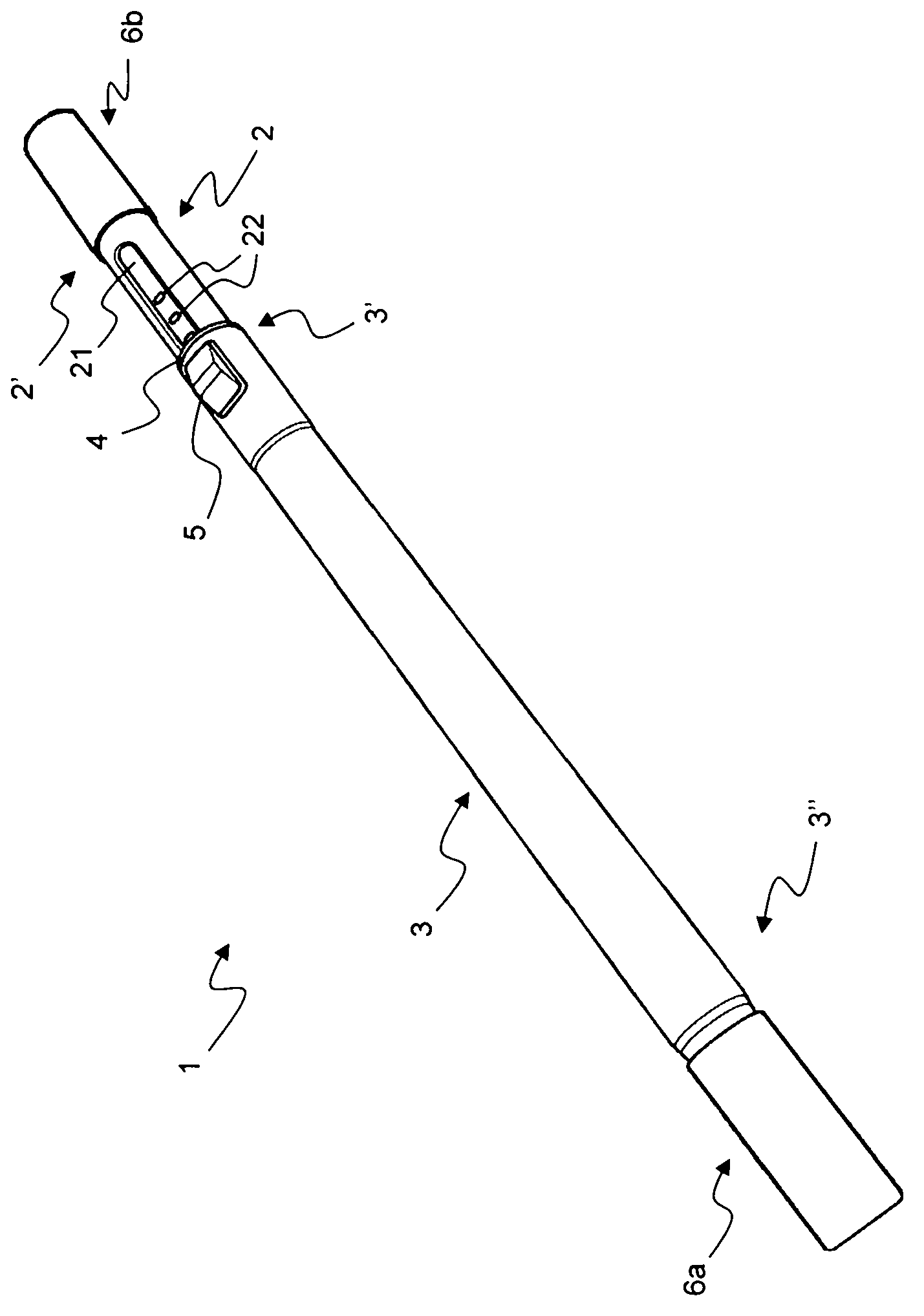
[0024] figure 1 A telescopic extension 1 according to an embodiment of the invention is shown.

[0025] The telescopic extension 1 comprises an inner tube 2, an outer tube 3, a sleeve 4, a restraint device (in figure 1 not shown), advancing the slider (in the figure 1 not shown in ) and operation button 5.

[0026] The inner tube 2 has a first end (or input end) 2' and a second end (or output end) (not shown in the figures). The outer tube 3 has a first end (or input end) 3' and a second end (or output end) 3". The telescoping extension 1 thus has an input end of the inner tube 2 as input end 2' and the output end 3" of the outer tube 3 as the output end.

[0027] The inner tube 2 has a substantially circular cross section. The outer surface of the inner tube 2 comprises an axial groove 20 having a bottom wall 21 in which a row of notches 22 of predetermined shape are formed.

[0028] The inner tube 2 and the outer tube 3 are able to slide sealingly one inside the other....


PUM


Abstract

A metal tube of an extension for a vacuum cleaner or the like is described. The metal tube is configured to be coupled to a tool, another tube or a connection device. The metal tube comprises, on a sidewall thereof and in the proximity of an end thereof, a recess extending in a radial direction towards the interior of the tube. The recess has a closed bottom and sidewalls which connect the closed bottom to the sidewall of the tube. One of said sidewalls is substantially perpendicular to a longitudinal axis of the tube.

Description

technical field [0001] The invention generally relates to segments of household appliances. More specifically, the present invention relates to metal pipes for household appliances such as vacuum cleaners. Even more specifically, the present invention relates to metal pipes for vacuum cleaners shaped with engaging means for suction tools or connection equipment. The tube may be, for example, a tube of a telescoping extension. Background technique [0002] For the purposes of the present invention, the term "vacuum cleaner" will be used in a broader sense so as to include all appliances for professional or domestic use which clean by suction. Thus, the term "vacuum cleaner" shall include standard vacuum cleaners, electric brooms, so-called heavy-duty drum vacuum cleaners, and vapor distribution and extraction appliances. During the course of this description reference will be made primarily to telescoping extensions, but the invention is not limited to the tubes of these e...

Claims


Application Information

Patent Timeline
IPC IPC(8): A47L9/24A47L9/00F16L9/02F16L37/091
CPCA47L9/244
Inventor S·卡纳尔
Owner OMEC SPA
Why Eureka
Try Eureka