Double-outrigger type cable beam anchoring structure of bridge steel box girder

A cable-girder anchoring and steel box technology, applied in bridges, bridge parts, bridge construction, etc., can solve the problems of large force, static strength and fatigue strength are not easy to meet design requirements, etc., to overcome stress concentration, improve stress safety effect

Active Publication Date: 2013-02-06
CHINA RAILWAY SIYUAN SURVEY & DESIGN GRP
View PDF6 Cites 15 Cited by
  • Summary
  • Abstract
  • Description
  • Claims
  • Application Information

AI Technical Summary

Problems solved by technology

[0006] The lug plate anchoring structure transmits the cable force directly to the side longitudinal web through the lug plate, and the side longitudinal web and lug plate bear a large for

Method used


Image

  • Double-outrigger type cable beam anchoring structure of bridge steel box girder
  • Double-outrigger type cable beam anchoring structure of bridge steel box girder
  • Double-outrigger type cable beam anchoring structure of bridge steel box girder

Examples


Embodiment Construction

[0031] Below in conjunction with accompanying drawing and embodiment the present invention is described in further detail:

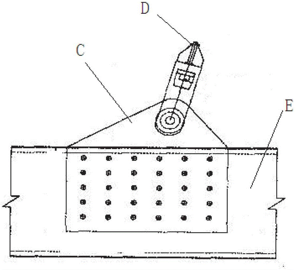
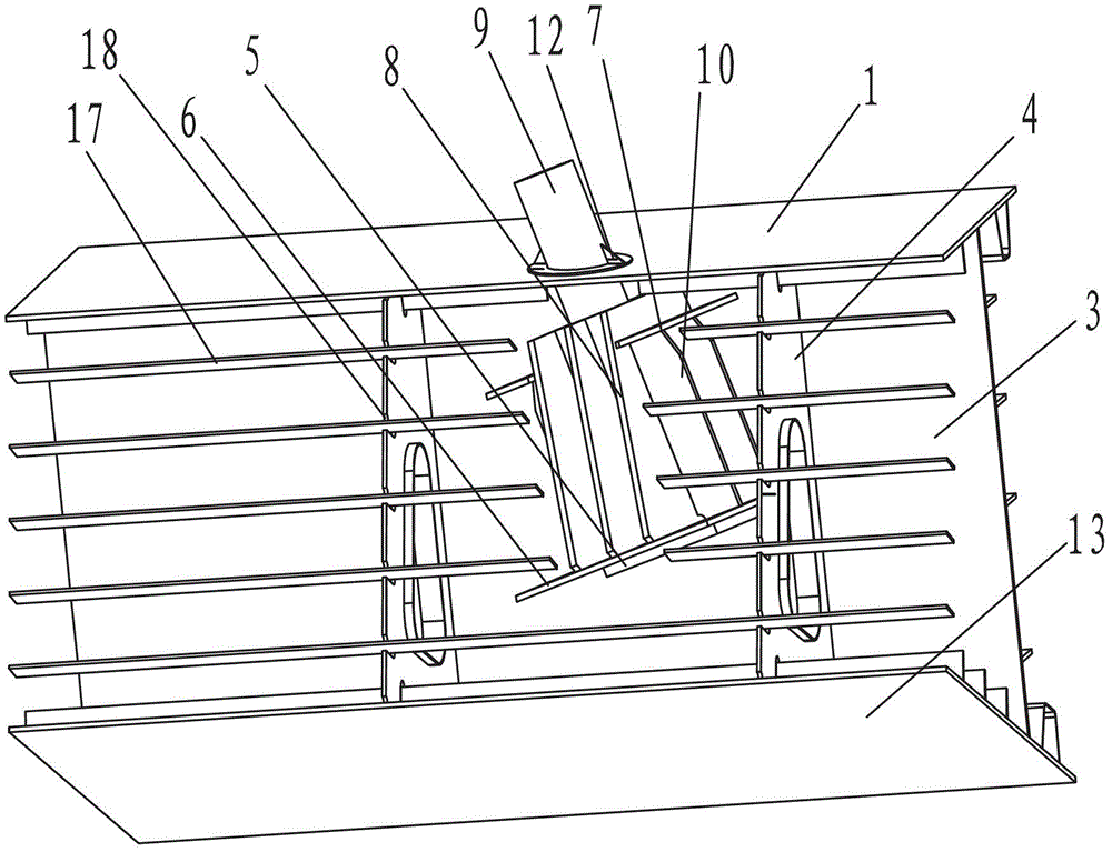
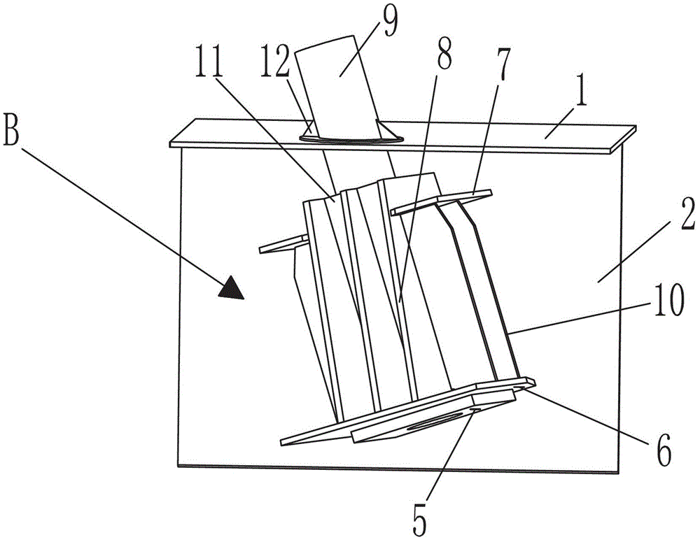
[0032] Such as Figure 2~6 The shown bridge steel box main girder double-slung cable beam anchorage structure includes a steel box main girder A mainly composed of a top plate 1, a side plate 2, a side longitudinal web 3, a bottom plate 13 and a diaphragm 4, and it also includes The anchor box B is used to transmit the force of the stay cables to the steel box girder A. The cable sleeve 9 of the anchor box B runs through the roof 1. The box body of the anchor box B is located in the steel box girder A, and the anchor Both sides of the box body of box B are welded with the side plate 2 and the side longitudinal web 3 respectively.

[0033] In the above technical solution, the anchor box B includes an anchor plate 5, a pressure bearing plate 6, a transverse support plate 7, a plurality of longitudinal support plates 8, and a cable sleeve 9 passing through...


PUM


Abstract

The invention discloses a double-outrigger type cable beam anchoring structure of a bridge steel box girder, comprising a steel box girder which is mainly formed by a top plate, a side plate, a side longitudinal web, a bottom plate and a transverse diaphragm plate. The double-outrigger type cable beam anchoring structure of the bridge steel box girder is characterized by also comprising an anchor box which is used for transferring the force of a stay cable to the steel box girder; a cable sleeve of the anchor box penetrates through the top plate; the body of the anchor box is located in the steel box girder; and two sides of the body of the anchor box are fixedly connected with the side plate and the side longitudinal web respectively. Through the double-outrigger type cable beam anchoring structure of the bridge steel box girder, the stress safety, the force transfer reliability and the fatigue resistance of the cable beam anchoring structure of the steel box girder are improved and the problem that the existing cable anchoring structures in common use have concentrated stress and overlarge local stress and fatigue stress is well overcome.

Description

technical field [0001] The invention relates to the technical field of bridge structures, in particular to a bridge steel box girder double pick type cable girder anchorage structure. technical background [0002] The connection structure of the cable-stayed steel box girder cable-stayed bridge and the steel girder (i.e., the cable-beam anchorage structure), as a structure that directly bears and transmits the force of the cable-stayed cables, is the most critical and complex stress-bearing structure of the steel box girder. one of the regions. [0003] According to the structural form, the cable beam anchorage structure of the steel box girder is generally divided into three types: lug plate type, anchor tie plate and anchor box. The lug-plate anchoring structure is a lug C protruding upward from the side longitudinal web of the main beam, and the cable D is anchored on the lug, and the pin-hinge connection is adopted, and the cable force is directly transmitted from the l...

Claims


Application Information

Patent Timeline
IPC IPC(8): E01D19/00E01D19/14E01D19/16
Inventor 罗世东刘振标潘茂盛曾甲华万信华陈可聂利芳王国彬
Owner CHINA RAILWAY SIYUAN SURVEY & DESIGN GRP
Why Eureka
Try Eureka