Constant load control device and method of bridge erecting machine

A technology of a control device and a bridge erecting machine, which is applied in the direction of erecting/assembling bridges, bridges, and bridge construction, can solve problems such as increasing construction costs and increasing construction risks, and achieves improved bending resistance and increased hoisting weight limit. value, the effect of reducing the cost of measures

Active Publication Date: 2019-06-28
SHANGHAI CONSTRUCTION GROUP
View PDF6 Cites 0 Cited by
  • Summary
  • Abstract
  • Description
  • Claims
  • Application Information

AI Technical Summary

Problems solved by technology

[0004] The purpose of the present invention is to provide a dead load control device and method of a bridge erecting machine, which can solve the existing method of setting strong temporary consolidation measures near the bridge pier to offset the unbalanced bending moment, and improve the control during the construction process Requirements, but also increase the construction cost, while increasing the construction risk

Method used


Image

  • Constant load control device and method of bridge erecting machine
  • Constant load control device and method of bridge erecting machine
  • Constant load control device and method of bridge erecting machine

Examples


Embodiment Construction

[0039] In order to make the above objects, features and advantages of the present invention more comprehensible, the present invention will be further described in detail below in conjunction with the accompanying drawings and specific embodiments.

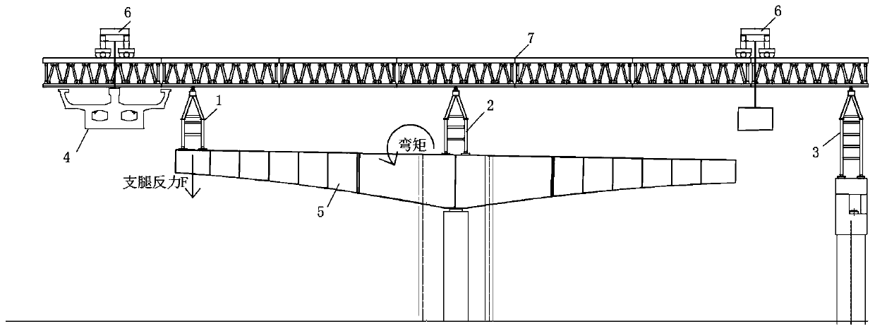
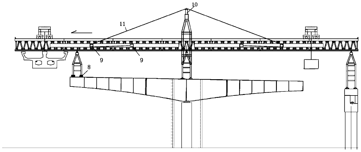
[0040] Such as Figure 1~3 As shown, the present invention provides a constant load control device for a bridge erecting machine, including:

[0041] Pressure sensor 8, said pressure sensor 8 is arranged on the bottom of the front leg 1 of the bridge erecting machine of the installed cantilever beam section 5, said pressure sensor measures the reaction force data F of the front leg in real time, and will measure the reaction force The data is transmitted to the control system through the wireless transmission module;

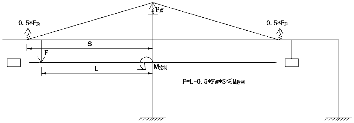
[0042] Jack 10, the jack is arranged on the middle leg 2 of the bridge erecting machine of the installed cantilever beam section 5, wherein the rear leg 3 of the bridge erecting machine is arranged on the pier, and...


PUM


Abstract

The invention provides a dead load control device and method of a bridge erection machine. The invention changes the stress form of the traditional bridge erecting machine, the cantilever hoisting load of the bridge erecting machine is transferred to the middle leg, the function of wireless active control of bridge erection machine reaction force is realized, intelligent control is realized, the cantilever load in front of the bridge erecting machine can be adjusted according to the hoisting weight and the hoisting distance, so as to control the front leg reaction force of the bridge erectingmachine to be within the target range, to control the bending moment of the construction beam section caused by the front leg reaction force F of the bridge erecting machine, to improve the stress safety of the construction beam section, to reduce the cost of measures in the hoisting construction, to improve the bending resistance of the main longitudinal beam of the bridge erecting machine, and to increase the original hoisting weight limit value of the bridge erecting machine.

Description

technical field [0001] The invention relates to a constant load control device and method of a bridge erecting machine. Background technique [0002] The bridge erecting machine is mainly used in the assembly construction of prefabricated bridges. Generally, 2 to 3 outriggers are erected on the bridge pier or the installed beam section to support the force. Generally, bridges with small spans are assembled at one time, and the outriggers of the bridge erecting machine are erected on the pier columns on both sides of the span. Bridges with large spans (greater than 50m) are generally assembled using the short-line method. The bridge erecting machine is supported by three outriggers—front, middle, and rear outriggers—respectively supported on the installed cantilever beam section and pier. [0003] Because the front outriggers are erected on the cantilever beam section, during the hoisting process of the prefabricated beam section, the beam section and the bridge pier will be...

Claims


Application Information

Patent Timeline
Patent Type & Authority Patents(China)
IPC IPC(8): E01D21/10
CPCE01D21/10
Inventor 况中华李鑫奎李兵周向阳沈志勇
Owner SHANGHAI CONSTRUCTION GROUP
Why Eureka
Try Eureka