Novel cooling and dedusting device

A dust removal device and a new type of technology, applied in the combustion of solid fuel, combustion equipment, lighting and heating equipment, etc., can solve problems such as changing the direction of biomass fire, and achieve the effect of extending service life, improving operating efficiency, and heating up quickly.

Inactive Publication Date: 2013-02-06
郭丰亮
View PDF0 Cites 2 Cited by
  • Summary
  • Abstract
  • Description
  • Claims
  • Application Information

AI Technical Summary

Problems solved by technology

[0004] The technical problem mainly solved by the present invention is to provide a new type of cooling and dedusting device, which can solve the problems of shortening the service life caused by the high internal temperature of the existing dedusting device and changing the direction of biomass fire, etc.

Method used


Image

  • Novel cooling and dedusting device

Examples


Embodiment Construction

[0012] The preferred embodiments of the present invention will be described in detail below in conjunction with the accompanying drawings, so that the advantages and features of the present invention can be more easily understood by those skilled in the art, so as to define the protection scope of the present invention more clearly.

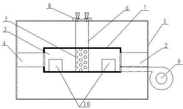
[0013] see figure 1 , the embodiment of the present invention includes: a furnace body 1, a furnace 3, a fire inlet 2 and a fire outlet 4 arranged at both ends of the furnace body 1 and communicating with the furnace 3, separated from the middle upper end of the furnace 3 and fixed to the furnace body 1 through a valve 8 The filter plate 6 is provided with an induced draft fan 9 at the lower end of the fire inlet 2. The induced draft fan 9 is arranged outside the furnace body 1 and communicates with the furnace 3 to drain the biomass fire, and directly enters the annealing furnace after dust removal. for heating.

[0014] Further, a cooling plat...


PUM


Abstract

The invention discloses a novel cooling and dedusting device which comprises a furnace body, a hearth, a fire inlet and a fire outlet which are arranged at two ends of the furnace body and are communicated with the hearth, and a filtering plate which is isolated at the upper end of the middle of the hearth and is fixed with the furnace body through a valve, wherein a draft fan is additionally arranged below the fire inlet; the draft fan is arranged outside the furnace body and is communicated with the hearth; and a cooling plate is fixedly arranged on the inner wall of the hearth. With the adoption of the cooling and dedusting device in such a mode, the problem that the service life is shortened due to the fact that the temperature inside the existing dedusting device is high is solved, and the direction of the biomass fire is changed; the device is simple in structure, easy to operate and relatively lower in production cost; and not only is the temperature rising speed in an annealing furnace accelerated, but also the quality of a workpiece machined in the annealing furnace is correspondingly ensured, thus the device has better practicability.

Description

technical field [0001] The invention relates to the field of biomass dust removal devices, in particular to a novel cooling and dust removal device. Background technique [0002] At present, in the process of using the biomass cracker and annealing furnace together, if the burner of the biomass cracker is directly heated against the annealing furnace, due to the fact that certain dust particles will be generated during the pyrolysis process of the biomass cracker, when the burner directly faces the annealing furnace When using a crucible furnace, dust particles will enter the annealing furnace along with the biomass fire, which will directly affect the production quality of the heated parts, so it is necessary to consider adding a dust removal device between the biomass cracker and the annealing furnace. [0003] The currently designed biomass dust removal device is to install a filter plate in the dust removal furnace to filter the dust particles by using the gravity an...

Claims


Application Information

Patent Timeline
Patent Type & Authority Applications(China)
IPC IPC(8): F23J15/02F23B80/04
Inventor 郭丰亮
Owner 郭丰亮
Why Eureka
Try Eureka