

Drainage structure for municipal garden
A drainage structure and garden technology, applied in drainage structures, waterway systems, water supply devices, etc., can solve the problems of wasting manpower to clean up, stagnant water on the ground, and rainwater can not be timely, so as to reduce reverse gushing, reduce blockage, reduce Cleverly designed effects
- Summary
- Abstract
- Description
- Claims
- Application Information
AI Technical Summary
Problems solved by technology
Method used
Image

Examples
Embodiment Construction
[0036] The present invention will be described in further detail below in conjunction with the accompanying drawings.
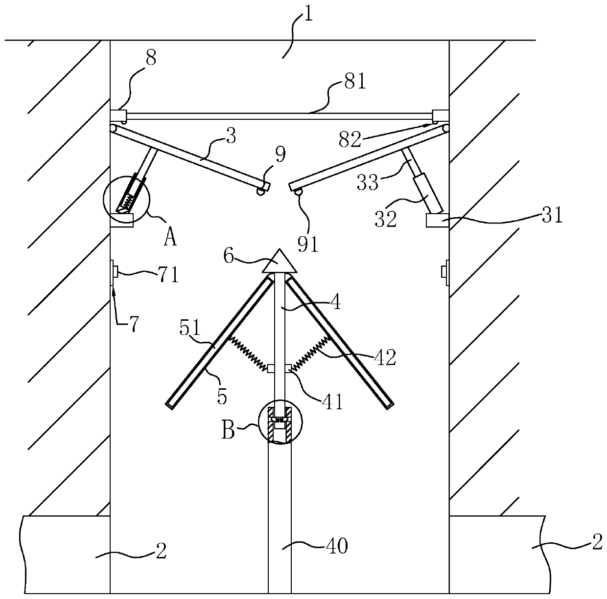
[0037] Present embodiment: a kind of municipal garden drainage structure, such as figure 1 with figure 2 As shown, it includes a shaft 1 and a drainage pipe 2. One end of the drainage pipe 2 is connected to the bottom of the shaft 1, and the other end is connected to the sewer, so that rainwater can be discharged from the sewer through the shaft 1 along the drainage pipe 2.
[0038] Rotating plates 3 are hinged on the inner walls of both sides of the shaft 1, and the rotating plates 3 are symmetrical to each other. An elastic supporting mechanism is arranged between the inner walls of the shaft 1, and the elastic supporting mechanism can not only support the rotating plate 3 at a predetermined position, but also play a certain role of buffering and shock absorption.
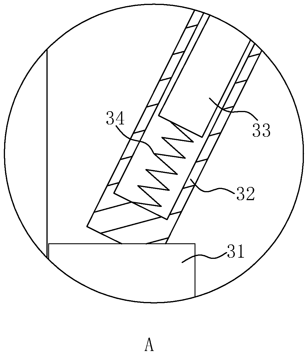
[0039]In this embodiment, the elastic support mechanism includes: a mounting plate 31 mou...
PUM
 Abstract
Description
Claims
Application Information