Fluid scrubber

a scrubber and flue gas technology, applied in the field of scrubbers, can solve the problems of high mixing degree between the gas and the scrubber liquid, and any suspended particles within the scrubber liquid, and achieve the effects of high mixing degree, efficient transfer, and high degree of turbulen

Active Publication Date: 2008-07-24
HEARTLAND WATER TECH INC
View PDF95 Cites 53 Cited by
  • Summary
  • Abstract
  • Description
  • Claims
  • Application Information

AI Technical Summary

Benefits of technology

[0023]During operation, polluted gas introduced through each tube mixes with the scrubbing liquid in a first confined volume formed by each weir, or each weir and walls of the vessel, and the tube(s), and the mixture of gas and liquid flows at high volume with a high degree of turbulence along the circulation path defined around each weir, thereby causing a high degree of mixing between the gas and the scrubbing liquid and any suspended particles within the scrubbing liquid. Shear forces within this two-phase or three-phase turbulent flow that result from the high density liquid phase overrunning the low density gas phase create extensive interfacial surface area between the gas and the scrubbing liquid that favors minimum residence time for mass and heat transfer between the liquid and gas phases to come to equilibrium compared to conventional gas dispersion techniques. Thus pollutants such as sulfur trioxide that might be present in the gas stream can be efficiently transferred to the scrubbing liquid, which might be water, in which case the sulfur trioxide would react with the water to form sulfuric acid, which would remain sequestered in the water. Also, vigorous mixing created by the turbulent flow hinders the formation of large crystals or precipitates within the scrubbing liquid and, because the system does not use small holes or other ports to introduce the gas into the scrubbing liquid, clogging and fouling associated with submerged gas reactors are significantly reduced or entirely eliminated. Further, the predominantly horizontal flow direction of the liquid and gas mixture over the top of the weir and along the surface of the scrubbing liquid within the reaction vessel enables the gas phase to disengage from the scrubbing liquid with minimal entrainment of liquid due to the significantly greater momentum of the much higher density liquid that is directed primarily horizontally compared to the low density gas with a relatively weak but constant vertical momentum component due to buoyancy.
[0024]In addition, a method of processing polluted gas using a fluid scrubber includes providing a scrubbing liquid to a reaction vessel at a rate sufficient to maintain the scrubbing liquid level at a predetermined level within the reaction vessel, supplying a polluted gas to the reaction vessel, adding a reagent to the scrubbing liquid to selectively react with a target pollutant in the gas and mixing the polluted gas and scrubbing liquid within the reaction vessel by causing the polluted gas and scrubbing liquid to flow around a weir within the fluid scrubber to thereby facilitate both transfer of the target pollutant to the scrubbing liquid and cause a desirable chemical reaction between the target pollutant and the selected reagent in order to render the target pollutant less noxious. For example, by adding caustic (e.g., sodium hydroxide) to the scrubber fluid to react with sulfur trioxide, in this case the target pollutant in the gas stream, the caustic readily reacts with the sulfur trioxide to form a sulfate, for example sodium sulfate, and sequester the sulfate within the scrubber liquid as a dissolved solid.

Problems solved by technology

During operation, polluted gas introduced through each tube mixes with the scrubbing liquid in a first confined volume formed by each weir, or each weir and walls of the vessel, and the tube(s), and the mixture of gas and liquid flows at high volume with a high degree of turbulence along the circulation path defined around each weir, thereby causing a high degree of mixing between the gas and the scrubbing liquid and any suspended particles within the scrubbing liquid.

Method used


Image

  • Fluid scrubber
  • Fluid scrubber
  • Fluid scrubber

Examples


Embodiment Construction

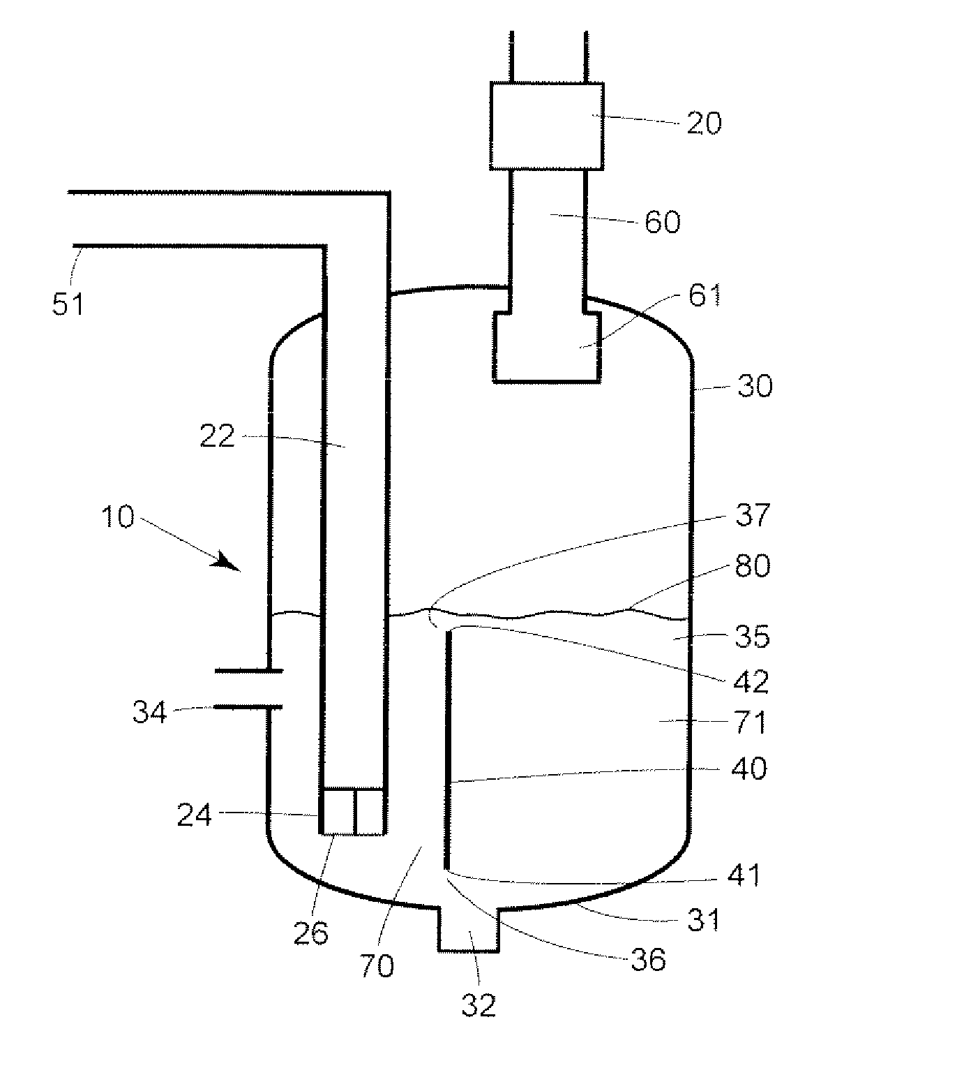
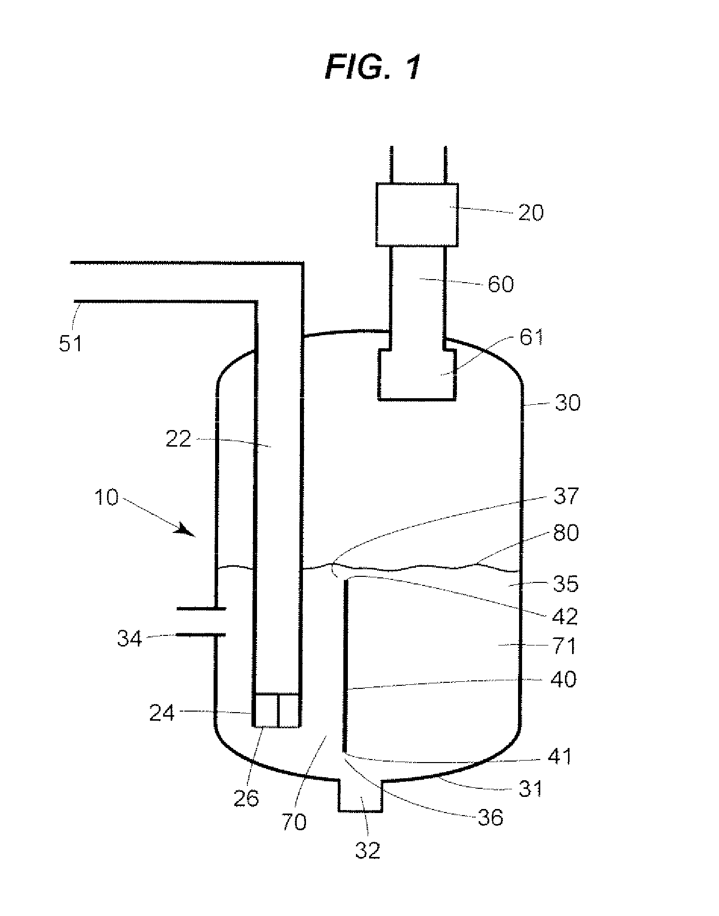
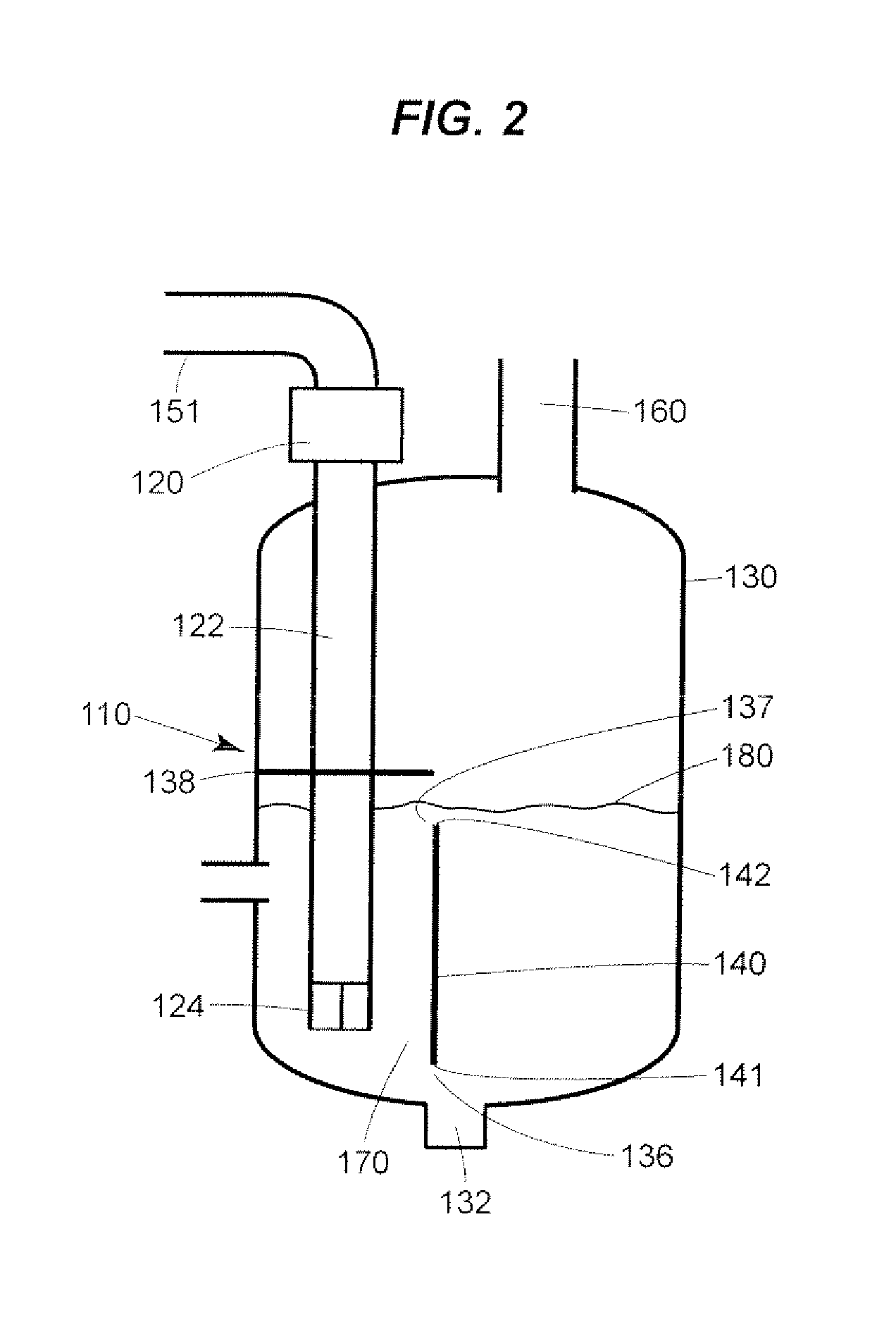
[0032]The performance of fluid scrubbers according to the disclosure depends on the properties of the pollutant(s) to be removed from the gas feed stream, the properties of the scrubbing liquid and the temperature and humidity of the gas feed stream. Usually, the gas feed stream is contaminated industrial exhaust. One skilled in the art will readily recognize that the advantages of fluid scrubbers according to the disclosure may be realized by substituting such fluid scrubbers for conventional fluid scrubbers in almost any fluid scrubbing application. Wherever fluid scrubbers according to the disclosure are employed, conventional means may be employed to control the flow of contaminated gas and scrubbing liquid through the fluid scrubber and, if required, to post-treat the liquid and / or gas streams. Likewise, most other conventional means of controlling fluid scrubbing systems to meet the requirements of a particular application may be employed. It will also be readily recognized th...


PUM

PropertyMeasurementUnit
distanceaaaaaaaaaa
diameteraaaaaaaaaa
diameteraaaaaaaaaa

Abstract

A fluid scrubber in the form of a submerged gas reactor includes a reaction vessel, a gas delivery lube partially disposed within the reaction vessel to deliver a gas into the reaction vessel and a scrubbing liquid inlet that provides a scrubbing liquid to the reaction vessel at a rate sufficient to maintain a controlled, constant level of fluid within the reaction vessel. A weir is disposed within the reaction vessel adjacent the gas delivery tube to form a first fluid circulation path between a first weir end and a wall of the reaction vessel and a second fluid circulation path between a second weir end and an upper end of the reaction vessel. During operation, gas introduced through the tube mixes with the scrubbing liquid and the combined gas and liquid flow at a high rate with a high degree of turbulence along the first and second, circulation paths defined around the weir, thereby promoting vigorous mixing and intimate contact between the gas and the scrubbing liquid. This turbulent flow develops a significant amount of interfacial surface area between the gas and the scrubbing liquid resulting in a reduction of the required residence time of the gas within the scrubbing liquid to achieve thermal equilibrium and / or to drive chemical reactions to completion, all of which leads to a more efficient and complete evaporation, chemical reaction, or combined evaporation and chemical reaction process.

Description

RELATED APPLICATIONS [0001]This application is a continuation-in-part of U.S. patent application Ser. No. 11 / 186,459, filed on Jul. 21, 2005, the entirety of which is hereby incorporated by reference.FIELD OF THE DISCLOSURE [0002]The disclosure relates generally to scrubbers, and more specifically, to fluid scrubbers that remove pollutants from gases.BACKGROUND [0003]Fluid scrubbers are generally used to remove pollutants found in contaminated gases, such as waste gases from industrial operations. Pollutants that maybe removed by fluid scrubbers include fumes, gases, particulate, and oil mists that might be carried in waste gas streams. Within fluid scrubbers, pollutants are transferred from a gas stream and sequestered within a scrubbing liquid by mechanisms that include inertial impaction, reaction with a sorbent or reagent slurry, or absorption into a liquid solvent.[0004]Scrubbing liquids are generally selected on the basis of costs and performance and may be solutions or slurri...

Claims


Application Information

Patent Timeline
Patent Type & Authority Applications(United States)
IPC IPC(8): B01D47/02
CPCB01D53/18B01D53/48B01D47/021Y02E50/346B01D2258/05Y02E50/30
Inventor DUESEL, BERNARD F.RUTSCH, MICHAEL J.
Owner HEARTLAND WATER TECH INC
Why Eureka
Try Eureka