
Bottom testing method

A test method and a technology for detecting components, which are applied in the direction of testing optical properties, measuring electricity, measuring devices, etc., can solve problems such as limiting the scope of application, and achieve the effect of wide applicability

Inactive Publication Date: 2013-02-06
SHENZHEN HI TEST SEMICON EQUIP
View PDF5 Cites 1 Cited by
  • Summary
  • Abstract
  • Description
  • Claims
  • Application Information

AI Technical Summary

Problems solved by technology

In terms of the manufacturing process of light-emitting components, the way of bottom pins is easier to realize than the way of side pins, which limits the application range of the traditional side probe clamp lighting test method

Method used


Image

  • Bottom testing method

Examples


Embodiment Construction

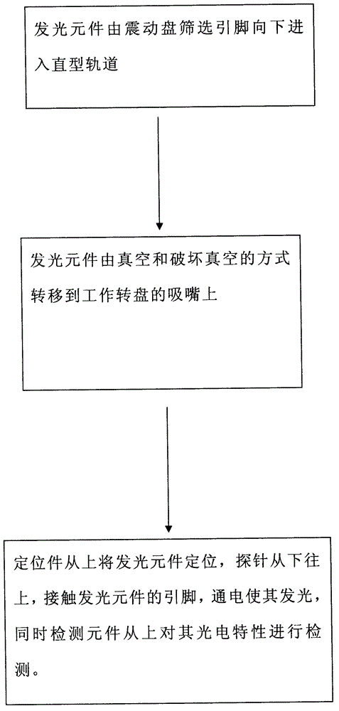
[0011] The present invention will be further described below with reference to the accompanying drawings and embodiments. see figure 1 , the present invention provides a preferred bottom testing method, the method steps comprising:

[0012] (1) The light-emitting element is screened by the vibrating plate and enters the straight track downward;

[0013] (2) The light-emitting element is transferred to the suction nozzle of the working turntable by vacuum and vacuum breaking;

[0014] (3) The positioning piece positions the light-emitting element from above, and the probe touches the pins of the light-emitting element from bottom to top, and energizes it to make it emit light. At the same time, the detection element detects its photoelectric characteristics from above.

[0015] The present invention is mainly aimed at the improvement of the light-emitting element testing method. The above description is only a preferred embodiment of the present invention, and it does not lim...


PUM


Abstract

The invention relates to a bottom testing method for electronic components. The bottom testing method is characterized by comprising the following steps that: a luminous element downwards enters a linear rail from a screening pin of a vibrating disc; the luminous element is transferred to a suction nozzle of a working turntable in a vacuum and vacuum-breaking mode; and the luminous element is positioned by a positioning piece from the upper part, a probe is contacted with the pin of the luminous element from bottom to top and is electrified to give out light, and a detection element detects the photoelectric characteristics from the upper part. The testing method can be suitable for a manufacturing process of the electronic components, and the testing range is wide.

Description

technical field [0001] The invention relates to a bottom testing method, and further relates to a bottom testing method of electronic components. Background technique [0002] Generally speaking, the main aspects of the optical parameters of electronic components are luminous flux, luminous intensity, luminous efficiency, wavelength, etc. Luminous efficiency characterizes the energy-saving characteristics of the light source, which is an important indicator to measure the performance of modern light sources. Therefore, electronic components must be tested before leaving the factory. [0003] At present, the commonly used testing methods for electronic components are side testing. The electronic components are adsorbed from the front end of the vibrating plate to the vacuum nozzle on the turntable by the feeding device. Tighten the pins of electronic components, power on, and detect. Since the method of the bottom pin is easier to realize than the way of the side pin in te...

Claims


Application Information

Patent Timeline
IPC IPC(8): G01M11/02G01R31/00
Inventor 卓维煌
Owner SHENZHEN HI TEST SEMICON EQUIP
Learn More