
Stacking and splitting quick detection method and device

A detection method and fast technology, applied in the field of data communication, can solve the problems of waste of bandwidth resources and CPU resources, poor compatibility, increase the complexity of protocol processing, etc., and achieve the effect of saving bandwidth resources and CPU resources.

Active Publication Date: 2013-02-06
MAIPU COMM TECH CO LTD
View PDF6 Cites 19 Cited by
  • Summary
  • Abstract
  • Description
  • Claims
  • Application Information

AI Technical Summary

Problems solved by technology

[0005] 1. BFD packets are sent before the stack system splits. Since the VSL link does not split most of the time, uninterrupted detection will undoubtedly cause a huge waste of bandwidth resources and CPU resources. When the detectio

Method used


Image

  • Stacking and splitting quick detection method and device
  • Stacking and splitting quick detection method and device
  • Stacking and splitting quick detection method and device

Examples


Example Embodiment

[0058] Embodiment 1: A stack system composed of two member devices performs stack split detection;

Example Embodiment

[0059] Embodiment 2: A stack system composed of multiple member devices performs stack split detection.

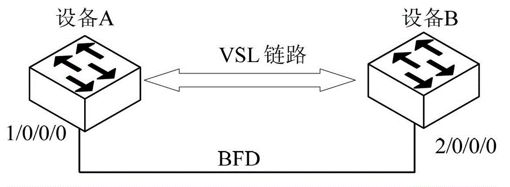
[0060] In the first embodiment, such as image 3 As shown, a stacking system composed of two member devices, member device A has better performance and richer functions, and its activity priority is set to high, and device B has lower performance. The activity priority is set to low, and the detection method uses standard BFD detection protocol for detection. The MAC address of device A is MAC_A, and the MAC address of device B is MAC_B. To further illustrate the steps, combine image 3 As shown in the stacking system, the rapid detection process of stack split is as follows Figure 4 As shown, including the following steps:

[0061] Step 401: The interface module of the member device A and the interface module of the member device B respectively create VLAN interfaces for the member devices where they are located, and set the created VLAN interface to a closed state. For eas...

Example Embodiment

[0069] In Example 2, such as Figure 5 In the stacking system shown, there are four member devices, device A, device B, device C, and device D. The activity priorities of the four member devices are device B, device A, device C, and device D from high to low. The performance of device B is the best, so the activity priority is set to the highest, and the IP address of the VLAN detection interface is set to the lowest. Combine Figure 5 As shown in the stacking system, the rapid detection process of stack split is as follows Image 6 As shown, including the following steps

[0070] Step 601: The interface modules of device A, device B, device C, and device D respectively create VLAN interfaces for the devices where they are located, and set them to a closed state. The four VLAN interfaces have the same VLAN ID and are named VLAN1, VLAN2, VLAN3, and VLAN4 in sequence.

[0071] Step 602: The interface modules of the four member devices bind IP addresses to the created closed VLAN in...


PUM


Abstract

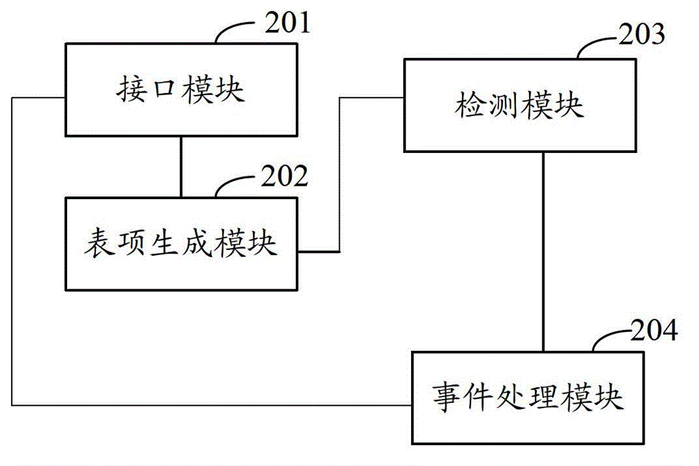
The invention discloses a stacking and splitting quick detection method, which comprises the following steps: A, each set of member equipment of a stacking system establishes a virtual local area network (VLAN) interface, configures address information on the VLAN interface and sets the VLAN interface to a closed state; B, the member equipment generates an address resolving table comprising the address information of other sets of member equipment according to an established stacking detection link; C, when a certain set of member equipment detects that a virtual exchange link has a fault, the member equipment starts the closed VLAN interface, establishes a bidirectional forwarding detection (BFD) session on the started VLAN interface, encapsulates a BFD detection message according to the address information in the address resolving table and interacts with the member equipment at the opposite end; and D, the member equipment of which the local BFD session reaches a hand-shaking finish UP sate compares a selection rule according to set main equipment, and when the member equipment is determined to be slave equipment by comparing source address information in the received BFD detection message with target address information, the member equipment closes all service interfaces. The invention also discloses a stacking and splitting quick detection device.

Description

technical field [0001] The present application relates to the field of data communication, in particular to stacking technology, and in particular to a method and device for quickly detecting stack splits. Background technique [0002] Stacking technology is to connect multiple network devices (the network devices are usually switches) together to form a stacking system through stacking cables, so as to provide as many ports as possible in a limited space; these network devices in the stacking system are collectively called stacking Member devices of the system. With the continuous improvement of network stability and equipment reliability requirements, the applicant proposed a virtual switching technology (VST, Virtual Switching Technology) for high-end network equipment on the basis of traditional stacking technology. Virtual switching technology is a technology based on a stacking system that virtualizes multiple physical devices into a single virtual device. The stackin...

Claims


Application Information

Patent Timeline
IPC IPC(8): H04L12/26H04L12/24H04L12/931
Inventor 徐海兵
Owner MAIPU COMM TECH CO LTD
Learn More