Electric double-supporting foot

A foot support, electric technology, applied in bicycle accessories, bicycle brackets, transportation and packaging, etc., can solve the problem of time-consuming and laborious, unable to lift the rear end of the vehicle, etc., and achieve the effect of high speed

Inactive Publication Date: 2013-02-13
常州市爱多动力科技有限公司
View PDF2 Cites 14 Cited by
  • Summary
  • Abstract
  • Description
  • Claims
  • Application Information

AI Technical Summary

Problems solved by technology

[0003] The disadvantage of the above-mentioned traditional double supports is that it is time-consuming and labor-intensive to use, especially for heavy-duty electric vehicles or motorcycles, and generally a single user cannot lift the rear end of the vehicle

Method used


Image

  • Electric double-supporting foot
  • Electric double-supporting foot
  • Electric double-supporting foot

Examples


Embodiment Construction

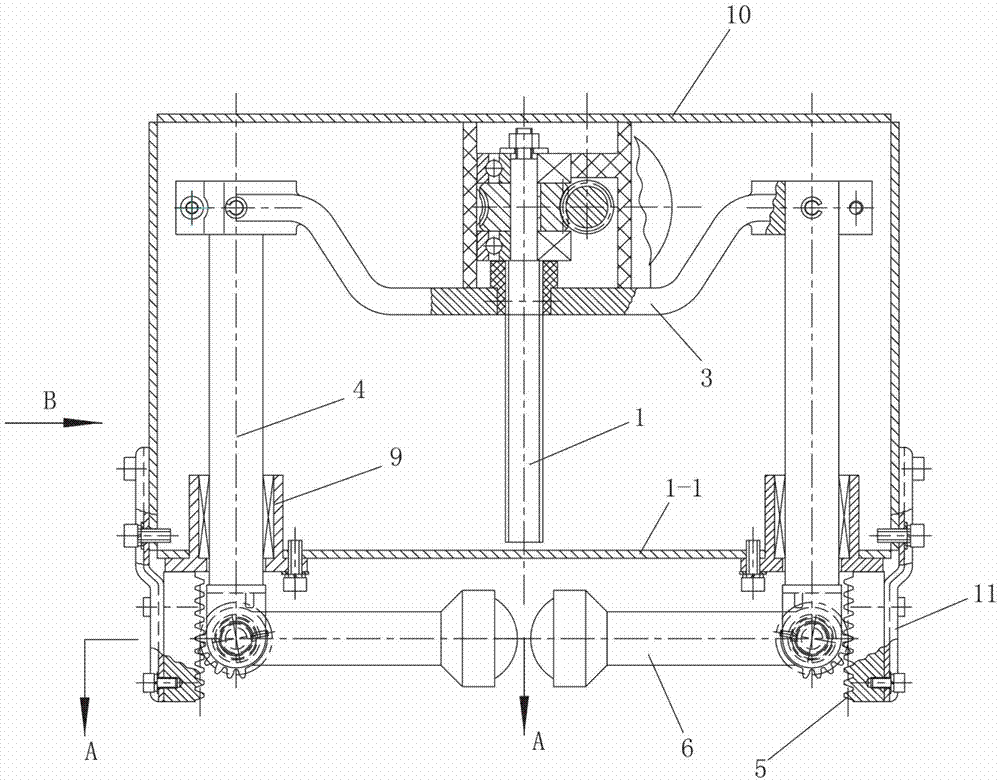
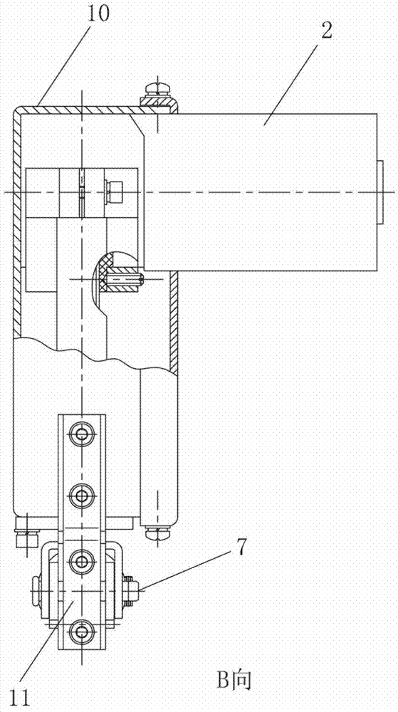
[0020] See Figure 1-3 , the electric double brace of this embodiment includes: a screw rod 1, a motor 2 connected to the screw rod 1 through a worm gear reducer, a beam 3, a strut 4 fixedly connected to both ends of the beam 3, A kick rod 6 hinged to the bottom of each strut 4. The crossbeam 3 and each strut 4 are arranged in the casing 10 , and the two sides of the bottom of the casing 10 are connected with the rack 5 through the fixing plate 11 .

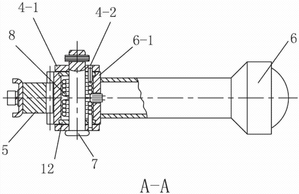
[0021] A shaft sleeve 6 - 1 is fixed on the top of the kick rod 6 , and the outer surface of the shaft sleeve 6 - 1 is a tooth surface; the tooth surfaces adjacent to each other mesh with the rack 5 .

[0022] The bottom end of the strut 4 is a U-shaped fork 4-1, and the axle sleeve 6-1 is hinged on the described U-shaped fork 4-1 through a pin 7; Inside, a torsion spring 8 is sheathed on the pin shaft 7, one end of the torsion spring 8 is connected to the bushing 6-1, and the other end of the torsion spring 8 is connected to t...


PUM


Abstract

The invention relates to an electric double-supporting foot which comprises a screw rod, a motor connected with the screw rod in a driving way, a beam in threaded match with the screw rod, supporting rods fixedly connected with the two ends of the beam, and supporting foot rods articulated with the bottom ends of all the supporting rods, wherein the outer side surface of the top end of each supporting foot rod is a tooth surface, and a rack suitable for being meshed with each tooth surface is fixedly arranged adjacently to the outer side of the tooth surface of each supporting rod. When the electric double-supporting foot is in use, the motor is controlled to control the screw rod to rotate, so as to control the up-and-down synchronous displacement of all the supporting rods through the beam; when all the supporting rods displace synchronously downwards, all the supporting foot rods swing downwards in place to be in an approximate reversed-V shape under the matching action of the racks and the tooth surfaces; and then, all the supporting rods continue to displace synchronously downwards till all the supporting rods are in contact with the ground and support the rear end part of an electric car or a motorcycle, so as to fix the vehicle. According to the electric double-supporting foot, the whole process can be completed through electric control without manpower, thereby facilitating the use of users. When the users want to use the electric car or the motorcycle, the supporting foot can be retracted automatically only in a way that the motor is controlled to act reversely.

Description

technical field [0001] The invention relates to a supporting device for an electric vehicle or a motorcycle, in particular to an electric double brace. Background technique [0002] The supporting devices for electric vehicles or motorcycles in the prior art are generally diagonal braces or double braces with tension springs, wherein the rear end of the electric vehicle or motorcycle needs to be lifted when the double braces are used, and then Use your feet to push the bipods into the hem position. [0003] The disadvantage of the above-mentioned traditional double legs is that it is time-consuming and labor-intensive to use, especially for heavy-duty electric vehicles or motorcycles, and generally a single user cannot lift the rear end of the vehicle. Contents of the invention [0004] The technical problem to be solved by the present invention is to provide an electric double stand with simple structure, easy to use and no effort. [0005] In order to solve the above-m...

Claims


Application Information

Patent Timeline
Patent Type & Authority Applications(China)
IPC IPC(8): B62H1/02
Inventor 刘云鹤蔡华勇孙云鹏孙道清
Owner 常州市爱多动力科技有限公司
Why Eureka
Try Eureka