Automatic finished-tire separation device

A technology for automatic separation and finished tires, applied in storage devices, transportation and packaging, etc., can solve the problems of limited length of multi-layer forks, high operation and maintenance costs, and high construction costs, and reduce one-time investment and recurring costs. , Improve work efficiency and economic benefits, reduce equipment costs

Inactive Publication Date: 2013-02-13
SHANDONG LOGISTIC TECH CO LTD
View PDF6 Cites 19 Cited by
  • Summary
  • Abstract
  • Description
  • Claims
  • Application Information

AI Technical Summary

Problems solved by technology

However, this mechanism has the following disadvantages: (1) a tire stopper is installed at the outbound port of each storage unit, which has high cost, complex structure, high operation and maintenance costs; There is damage, which affects the quality of the tire
However, this mechanism utilizes stackers and multi-layer forks to complete the storage of tires and has the following disadvantages: (1) Pneumatic push rods and pneumatic inserts are installed at the storage openings of each row of storage units, which has high cost, complicated structure, and difficult operation and maintenance. High cost; (2) The length of the multi-layer fork of the stacker is limited, and the number of rows of tires that can be stored at one time is limited. A three-dimensional warehouse requires multiple storage stackers or multiple lanes, and each stacker lane is relatively heavy. Wide, large footprint, serious waste of space
[0005] A small finished tire warehouse needs to meet the storage requirements of hundreds of varieties of finished tires, requiring thousands of storage units. The above two tire storage forms are installed at the exit or entrance of the tire warehouse with the power device that controls the tires entering and leaving the warehouse. One storage unit means that thousands of power devices are needed, and the cost of construction and operation is high
In addition, the failure rate of thousands of power units is high, and the finished tire warehouse is generally more than ten meters high, making maintenance difficult

Method used


Image

  • Automatic finished-tire separation device
  • Automatic finished-tire separation device
  • Automatic finished-tire separation device

Examples


Embodiment Construction

[0029] Describe the implementation process of the present invention in detail in conjunction with accompanying drawing, as Figure 1-Figure 8 shown.

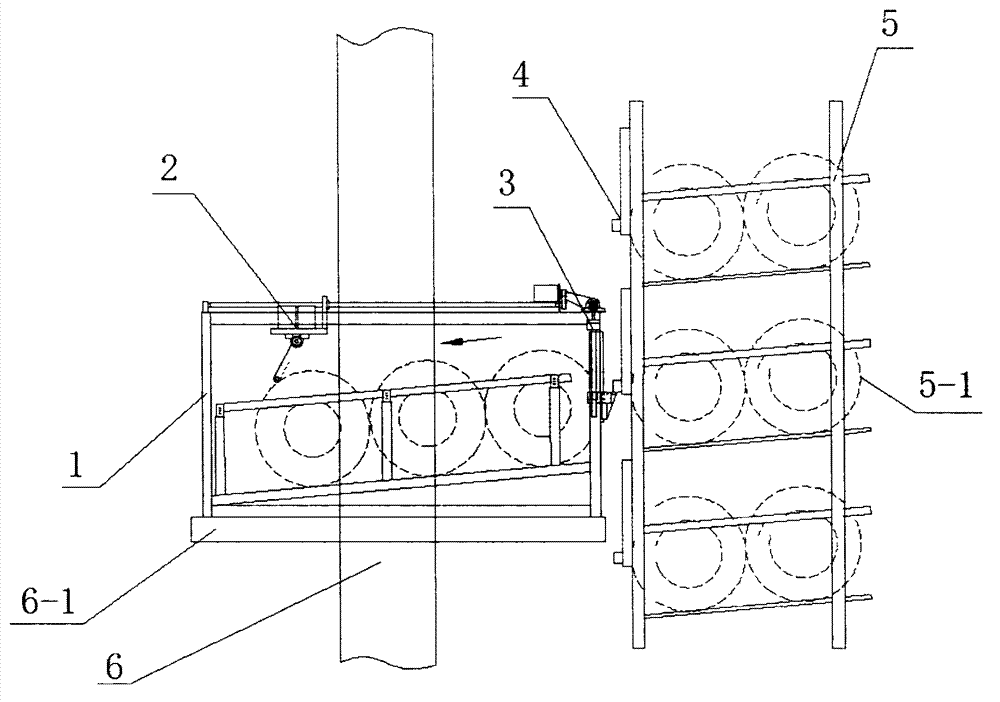
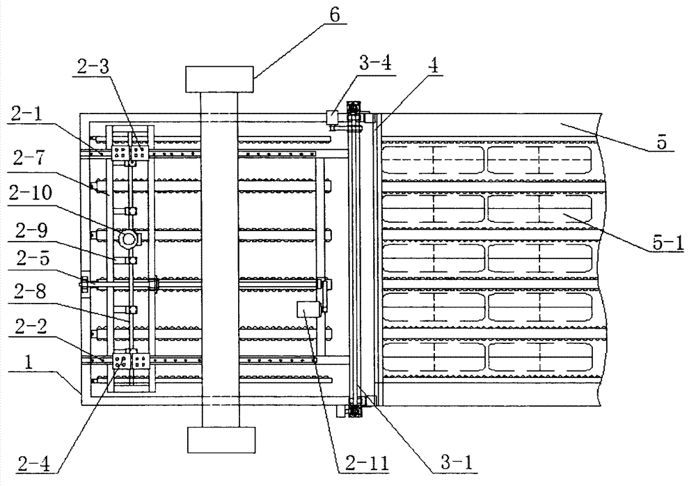
[0030] The present invention is composed of a tire temporary storage box 1, a tire release mechanism 2 installed on the tire temporary storage box, a finished tire storage exit gate lifting mechanism 3 and an exit gate mechanism 4 installed at the finished tire storage exit. On the cargo platform 6-1, it corresponds to the outlet of the finished tire storehouse 5.

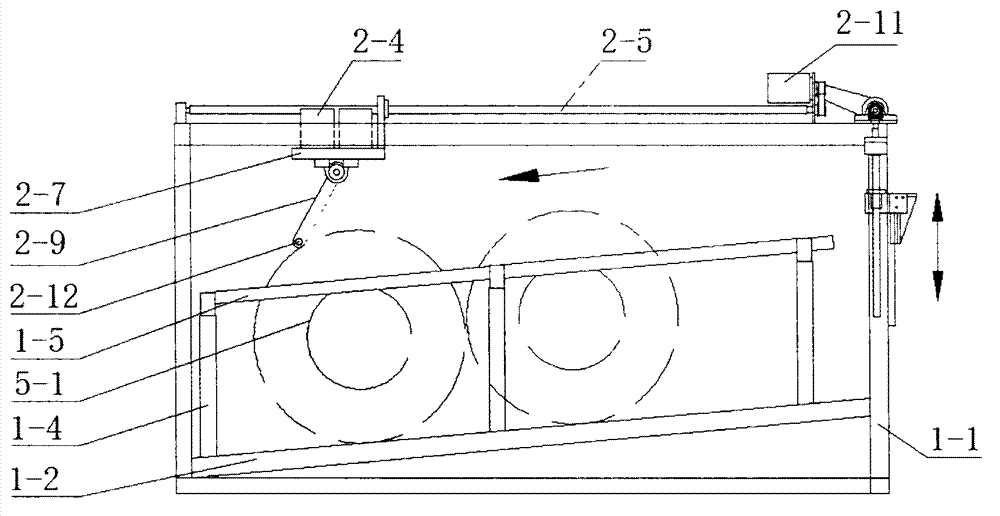
[0031]The tire temporary storage box 1 is composed of a rectangular frame 1-1, an inclined base plate 1-2, a guide rail support beam A1-3-1, a guide rail support beam B1-3-2, a tire rolling guide bracket 1-4, and a fluent strip 1-5 Composition; the rectangular frame is composed of four longitudinal beams, four beams, and four columns fixed together. The length of the beam is determined according to the number of rows of tires taken at one time, and the length of the...


PUM


Abstract

The invention relates to logistic equipment, in particular to an automatic finished-tire separation device which is arranged on a loading platform of a stacker for movable equipment and used cooperatively with a finished-tire storehouse. The automatic finished-tire separation device comprises a temporary tire storage box, a tire release mechanism, a finished-tire storehouse exit gate lifting mechanism and an exit gate mechanism, wherein the tire release mechanism is arranged on the temporary tire storage box, and the exit gate mechanism is arranged on a finished-tire storehouse exit. The movable equipment is controlled according to the command sent by control software of a control system, thus the finished tires can be separated automatically when being stored in and taken out of the storehouse. The automatic finished-tire separation device is used cooperatively with the stacker and the finished-tire storehouse, thus the structures of the equipment are simplified, the equipment cost is lowered, and the one-time investment and recurrent expenses of users are saved. The automatic finished-tire separation device is simple in structure, large in range of operation, flexible to operate and convenient to maintain, and the work efficiency and the economic benefit are greatly improved.

Description

1. Technical field [0001] The invention relates to logistics equipment, in particular to an automatic separation device for finished tires. 2. Background technology: [0002] The development of the tire industry has promoted the development of storage technology and equipment for finished tires. In order to improve the efficiency of tire storage and reduce physical labor, tire storage technology and equipment have been improved in recent years. [0003] The Patent Office of the State Intellectual Property Office of China announced on December 1, 2010 a "tire vertical storage system" with the announcement number CN201660273, which consists of a tire storage mechanism, a tire lifting mechanism, a damping tire landing mechanism, a tire stopper etc. The tires enter the tire storage mechanism through the lifting mechanism for storage, and complete the exit through the tire stopper and the damping tire drop mechanism. However, this mechanism has the following disadvantages: (1)...

Claims


Application Information

Patent Timeline
Patent Type & Authority Applications(China)
IPC IPC(8): B65G1/04B65G1/137
Inventor 张小艺刘鹏张怡弓姜凯
Owner SHANDONG LOGISTIC TECH CO LTD
Why Eureka
Try Eureka