Heat recovery device

A technology of heat recovery device and air inlet pipe is applied in the field of heat recovery device, which can solve the problems of heat loss, insufficient heat absorption by heat exchanger, energy waste, etc., so as to reduce the usage amount, improve the usage efficiency, and improve the operating environment. Effect

Active Publication Date: 2013-02-13
JIANGSU SANYANG ENVIRONMENTAL ENG
View PDF12 Cites 3 Cited by
  • Summary
  • Abstract
  • Description
  • Claims
  • Application Information

AI Technical Summary

Problems solved by technology

[0002] The gas-fired curing chambers commonly used in the past such as figure 1 As shown, this curing chamber includes a main box 1, a sub-box 2 on the top of the main box, a burner 3 in the box, a

Method used


Image

  • Heat recovery device
  • Heat recovery device
  • Heat recovery device

Examples


Embodiment Construction

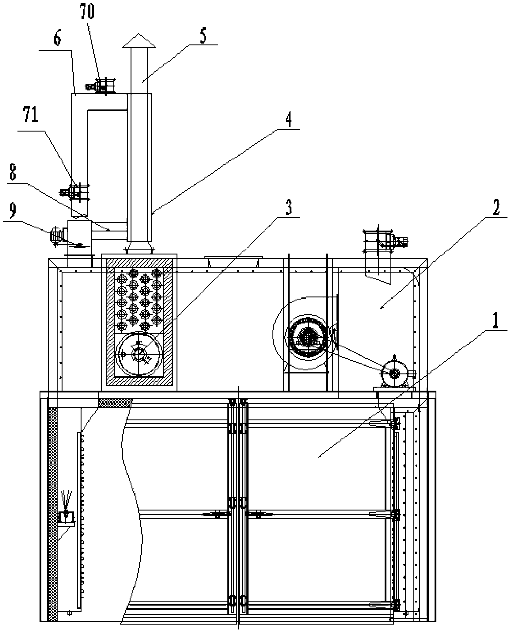
[0018] The present invention will be further described below in conjunction with accompanying drawing.

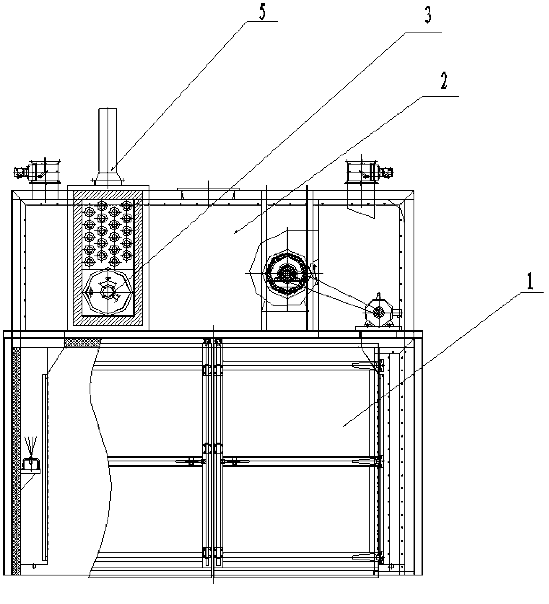
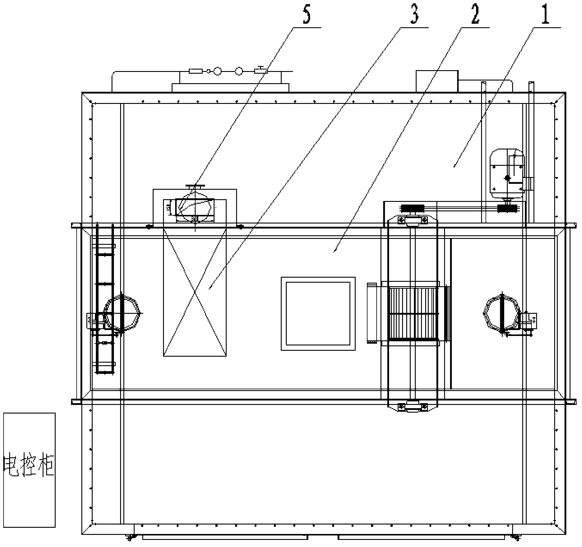
[0019] like Figures 3 to 4 As shown, a heat recovery device is mainly composed of a main box 1, an auxiliary box 2, a burner 3, a burner exhaust pipe 5, a heat recovery device 4, an air inlet pipe 6, and The upper pneumatic valve 70, the lower pneumatic valve 71, the air outlet pipe 8 and the mixed flow fan 9, the exhaust pipe 5 of the burner connected to the burner 3 is provided with a heat recovery device 4, and the upper part of the heat recovery device 4 has an air inlet pipe 6. The air inlet pipe 6 is connected to the main box body 1. An upper pneumatic valve 70 is installed on the upper part of the air inlet pipe 6 to allow natural wind to enter. The lower part of the air inlet pipe 6 is equipped with a lower pneumatic valve 71 to allow circulation air to enter; heat recovery The bottom of device 4 is equipped with air outlet pipe 8, and air outlet pipe 8 is conne...


PUM


Abstract

A heat recovery device for a gas curing chamber is characterized in that a fin plate is arranged in the heat recovery device; an air inlet pipe on the upper part of the heat recovery device is connected with a main box body; a pneumatic valve is respectively mounted on the upper part and the lower part of the air inlet pipe; an air outlet pipe is mounted on the lower part of the heat recovery device; a mixed flow fan is mounted in the air outlet pipe; and an outlet of the mixed flow fan is connected with an auxiliary box body. The heat recover device for the gas curing chamber is economic and practical, simple in structure, and convenient to manufacture, and can improve the energy utilization efficiency, lower the operation cost of enterprises, and conform to the policies of energy conservation and emission reduction.

Description

technical field [0001] The invention relates to a heat recovery device, in particular to a heat recovery device for recycling high heat discharged from a burner. The device is suitable for heat recovery in a curing chamber in a combustion mode. Background technique [0002] The gas-fired curing chambers commonly used in the past such as figure 1 As shown, this curing chamber includes a main box 1, an auxiliary box 2 on the top of the main box, a burner 3 in the box, and the gas of the burner 3 is absorbed by the heat exchanger and discharged by the exhaust pipe 5. Heater absorbs heat insufficiently, has a large amount of heat loss, causes energy waste. Contents of the invention [0003] Aiming at the problems existing in the prior art, the purpose of the present invention is to provide a heat recovery device to improve the efficiency of energy use and achieve the goals of energy saving, emission reduction, low-carbon and environmental protection. [0004] To achieve the ...

Claims


Application Information

Patent Timeline
IPC IPC(8): F27D17/00
Inventor 顾金杰王约倪王卫吴恒金科史春辉
Owner JIANGSU SANYANG ENVIRONMENTAL ENG
Why Eureka
Try Eureka