

Distributed flow control method for Ethernet switch
A technology of flow control and switch, which is applied in the direction of data exchange network, digital transmission system, electrical components, etc., can solve the problem of switch SW1 whole machine switching performance degradation, etc., and achieve the effect of normal forwarding and fast flow control
- Summary
- Abstract
- Description
- Claims
- Application Information
AI Technical Summary
Problems solved by technology
Method used
Image

Examples
Embodiment Construction
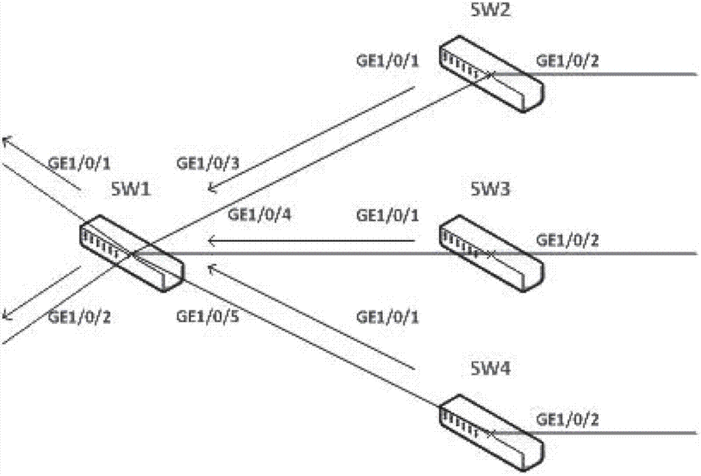
[0026] see Figure 5 A distributed flow control method for an Ethernet switch, comprising the following steps:
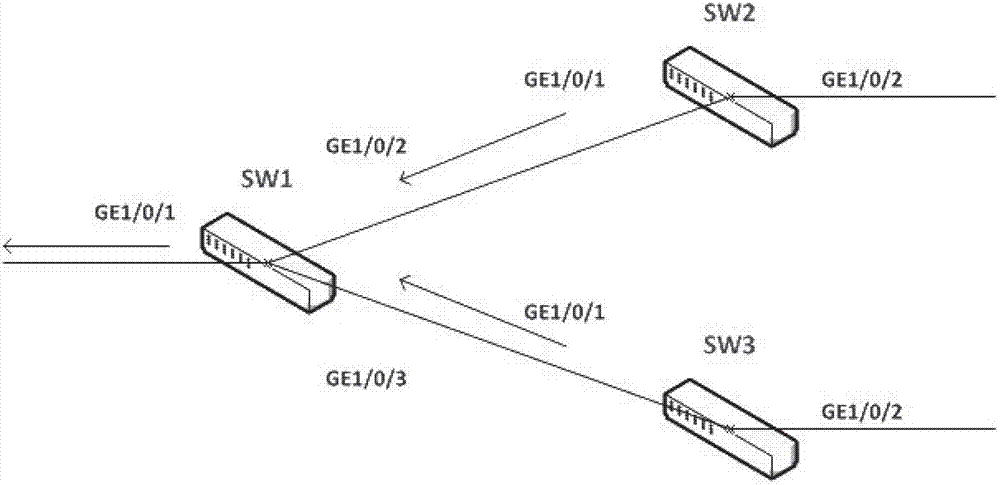
[0027] a. The source switch sends scheduled traffic to the forwarding switch, which causes congestion on the forwarding switch; the scheduled traffic is only related to the size of the traffic, not the content of the traffic, and this traffic can cause congestion on the forwarding port of the forwarding switch. The source switch is the switch that sends the traffic, the forwarding switch is the switch that forwards the traffic, and the congestion on the forwarding switch is the congestion on the forwarding port of the forwarding switch.
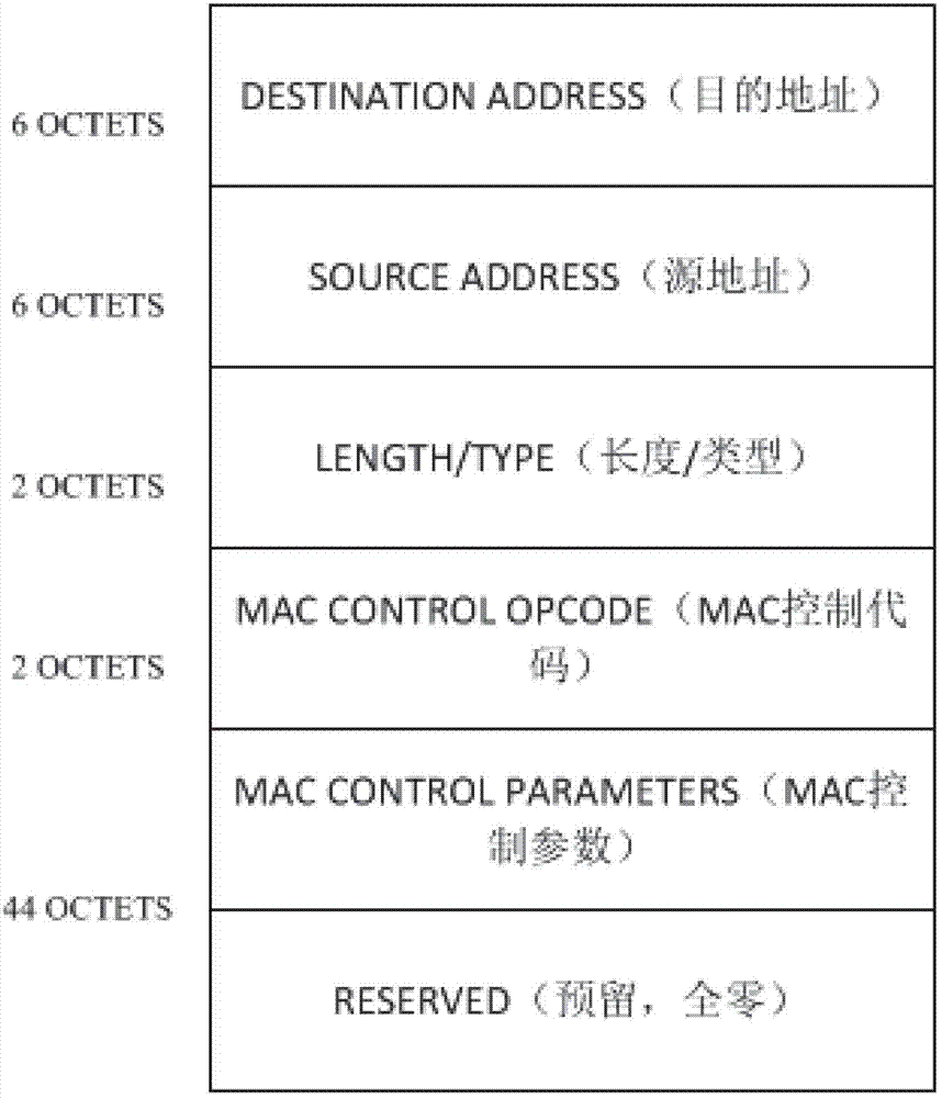
[0028] b. The forwarding switch organizes the destination address of the traffic passing through the congested port into a control packet, and sends the control packet to the source switch; this is to let the source switch know which traffic is currently being forwarded through the congested port of the forwarding switch .
[002...
PUM
 Abstract
Description
Claims
Application Information