Revolving cutting mechanism for one-die two-yield precise sleeve member

A technology of one mold, two outs, and sleeve parts, applied in the field of mold manufacturing, can solve the problems of deformation, the punch cannot be supported by the sleeve parts, and it does not have the ability to produce two precision sleeve parts at the same time.

Inactive Publication Date: 2013-02-20
JINHUA VOCATIONAL TECH COLLEGE
View PDF3 Cites 1 Cited by
  • Summary
  • Abstract
  • Description
  • Claims
  • Application Information

AI Technical Summary

Problems solved by technology

[0002] In the existing stamping die ring cutting mechanism, due to the dislocation of the upper and lower parts of the sleeve part during the cutting process, the punch cannot completely support the inside of the sleeve part, and the deepest support can only be supported to the inside of the uncut part of the sleeve part
Therefore, in the circumcision process, the excised part of the sleeve part will be deformed due to the lack of internal support of the punch, the cylindricity cannot be well guaranteed, and it cannot be used as a precision part. The excised part is generally discarded, wasting resources
Existing stamping dies do not have the function of producing two precision sleeve parts at the same time by using the circumcision mechanism

Method used


Image

  • Revolving cutting mechanism for one-die two-yield precise sleeve member
  • Revolving cutting mechanism for one-die two-yield precise sleeve member
  • Revolving cutting mechanism for one-die two-yield precise sleeve member

Examples


Embodiment approach

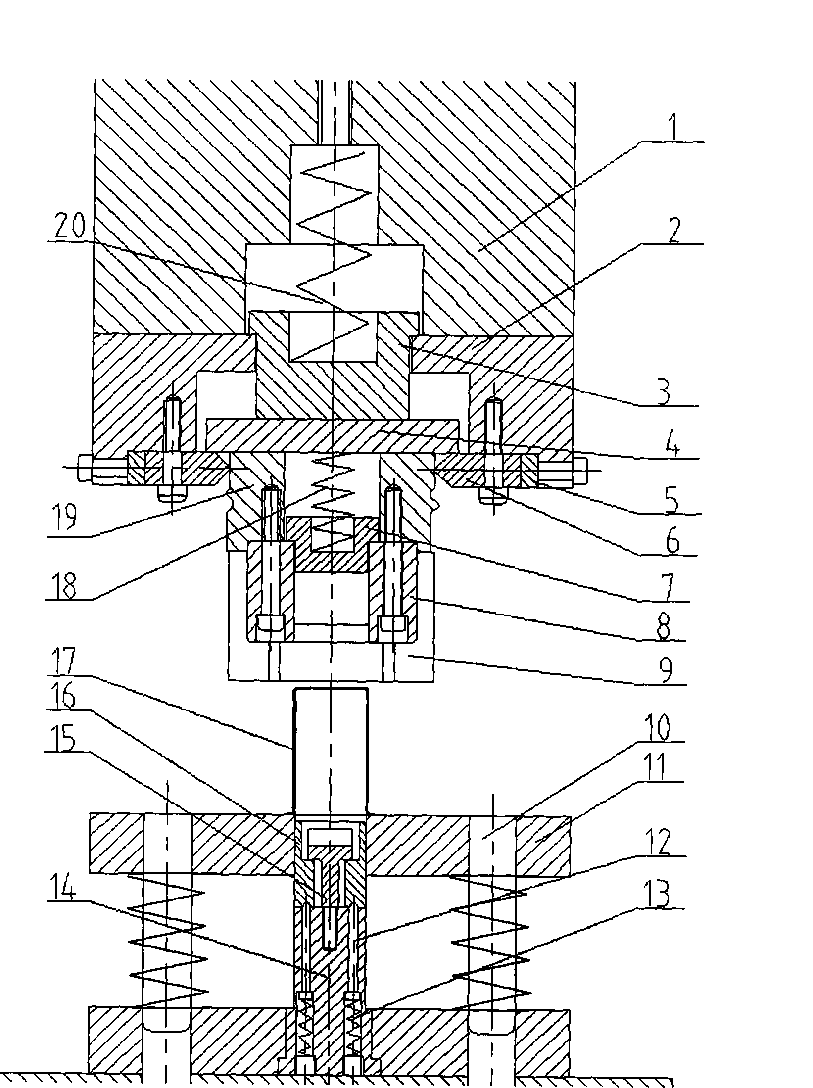
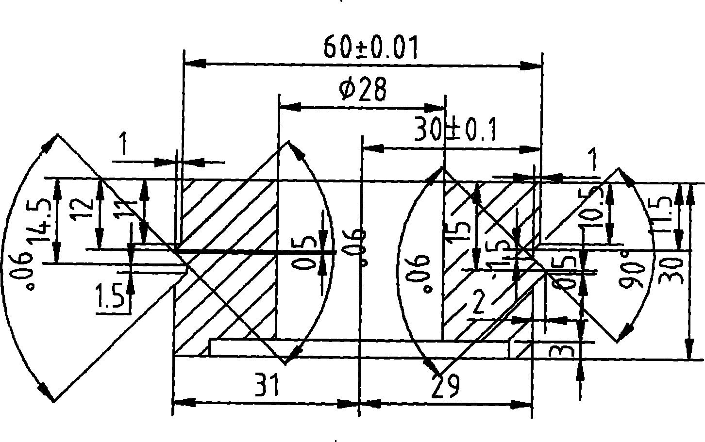
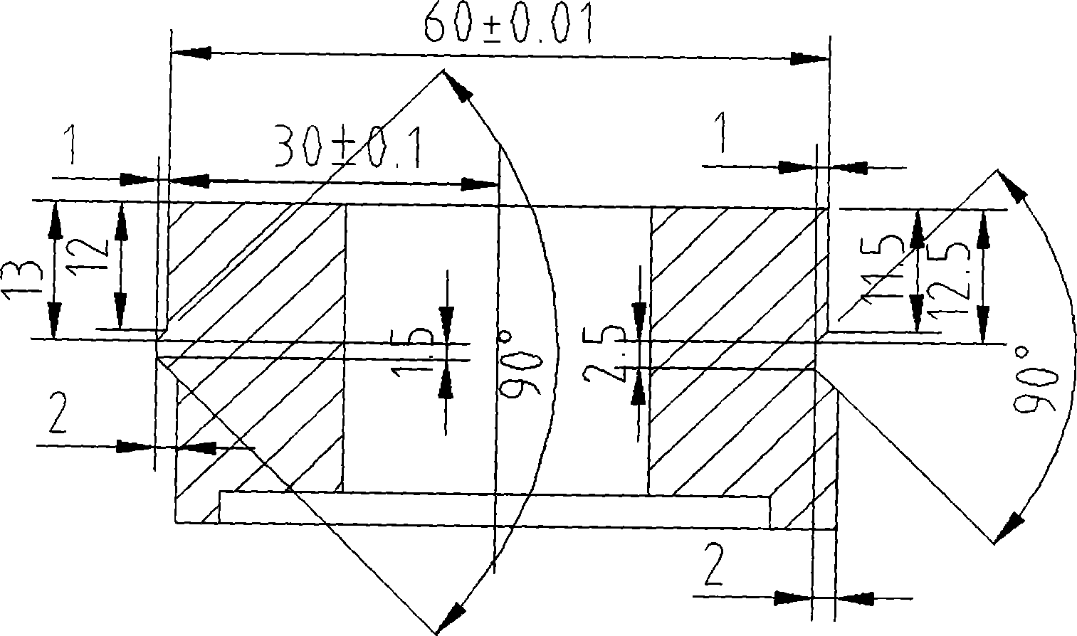
[0019] figure 1 It is a sectional view of an assembly of an embodiment of the present invention; figure 2 It is a front sectional view of a swing block according to an embodiment of the present invention; image 3 It is a left sectional view of the swing block according to the embodiment of the present invention; Figure 4 It is a perspective view of a swing block according to an embodiment of the present invention; Figure 5 It is a movement path diagram of the central axis of the ring-cut once ring-cut die according to the embodiment of the present invention.

[0020] like figure 1 As shown, the circumcision mechanism of one mold with two precision sleeve parts includes an upper mold part and a lower mold part, wherein:

[0021] The upper mold part includes a large empty pad 1, a small empty pad 2, and a swing block 19 in order from top to bottom. The space formed by the connection of the large empty pad 1 and the small empty pad 2 is provided with a large spring 20, a ...


PUM


Abstract

The invention discloses a revolving cutting mechanism for a one-die two-yield precise sleeve member. The revolving cutting mechanism comprises an upper die part and a lower die part. The upper die part comprises a large empty pad, a small empty pad and a swinging block; a large spring, a spring pad and a hanging plate are arranged in the large and the small empty pads; an adjusting block and power-assisted blocks are arranged on the small empty pad; the hanging plat is arranged on an upper part of the swinging block; a revolving cutting concave die and a limiting block are arranged on the lower part of the swinging block; and a middle spring and a top core are arranged in the swinging block. The lower die part comprises a discharging plate and a revolving cutting convex die; the revolving cutting convex die is arranged on a pedestal and corresponds to the revolving cutting concave die of the upper die part; a guide post is arranged on the discharging plate; a movable block and a limit pin are arranged on the revolving cutting convex die; and a pilot pin and a small spring are arranged in the revolving cutting convex die. The power-assisted blocks are respectively fixed at the front side, the back side, the left side and the right side of the lower empty pad of the upper die part; the inner sides of the power-assisted blocks are matched with the outer side of the swinging block; the end spherical surface of the pilot pin on the revolving cutting convex die is matched with the bottom of the movable block; and the movable block is tightly pressed by the small spring. According to the invention, two precise sleeve members required by a high cylinder degree can be simultaneously and efficiently cut, so that the cost is saved.

Description

technical field [0001] The invention relates to a ring cutting mechanism for stamping dies, more specifically relates to a ring cutting mechanism for precision sleeve parts with one die and two outputs, and belongs to the technical field of die manufacturing. Background technique [0002] In the existing stamping die circumcision mechanism, due to the dislocation of the upper and lower parts of the sleeve part during the cutting process, the punch cannot fully support the inside of the sleeve part, and the deepest support can only be supported to the inside of the uncut part of the sleeve part. Therefore, in the circumcision process, the excised part of the sleeve part will be deformed due to the lack of internal support of the punch, the cylindricity cannot be well guaranteed, and it cannot be used as a precision part. The excised part is generally discarded, wasting resources. Existing stamping dies do not have the function of simultaneously producing two precision sleeve...

Claims


Application Information

Patent Timeline
Patent Type & Authority Applications(China)
IPC IPC(8): B21D37/12
Inventor 徐振宇
Owner JINHUA VOCATIONAL TECH COLLEGE
Why Eureka
Try Eureka