Glasses Elastic Hinge

An elastic hinge and hinge technology, applied in glasses/goggles, optics, instruments, etc., can solve the problems of loss of elasticity of glasses feet, high processing cost, poor stability, etc., and achieve good anti-swing effect, high degree of firmness, and stability Good results

Inactive Publication Date: 2015-07-29
玉环市金富华眼镜科技股份有限公司
View PDF10 Cites 1 Cited by
  • Summary
  • Abstract
  • Description
  • Claims
  • Application Information

AI Technical Summary

Problems solved by technology

[0004] However, the outer end of the single-tooth core of the elastic hinge for this kind of spectacle frame is exposed outside the slingshot case, and only a part connected with the male buckle is located in the groove of the slingshot case. After installation, the outer end of the single-tooth core is located Between the double teeth of the hinge, if the gap between the double teeth of the hinge and the core of the single tooth is small, the friction between the double teeth of the hinge and the core of the single tooth will increase, and the temples will lose their grip during the opening and closing process. Elasticity or elasticity is very weak; if the gap between the double teeth of the hinge and the core of the single tooth is increased, the assembled spectacle temples will swing left and right, and the stability is poor, so in the process of processing, the distance between the double teeth of the hinge and the single tooth The diameter tolerance of the tooth core along its radial direction is very high, it is difficult to control in actual mass production, and the processing cost is high

Method used


Image

  • Glasses Elastic Hinge
  • Glasses Elastic Hinge
  • Glasses Elastic Hinge

Examples


Embodiment 1

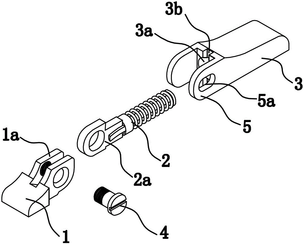
[0042] The glasses elastic hinge provided by the present invention is used for connecting glasses feet and glasses frames, such as figure 1 As shown, it includes a hinge head 1, a spring core 2, a slingshot shell 3 and a pin shaft 4.

[0043] The hinge head 1 is fixedly connected with the spectacle frame, the slingshot case 3 is fixedly connected with the spectacle feet, the spring core 2 is installed in the installation hole 3a of the slingshot case 3, and one end is the hinged end 2a located outside the installation hole 3a, the hinged end 2a It has a hinge hole for hinged connection with the hinge head 1. The slingshot shell 3 has a groove 3b that runs through the slingshot shell 3 up and down along the radial direction of the spring core 2 at the end face of one end of the mounting hole 3a, which is used for inserting inserts when hinged to facilitate the pulling out of the spring core 2. The slingshot shell 3 has two sheet-shaped single-teeth 5 parallel to the axial dire...

Embodiment 2

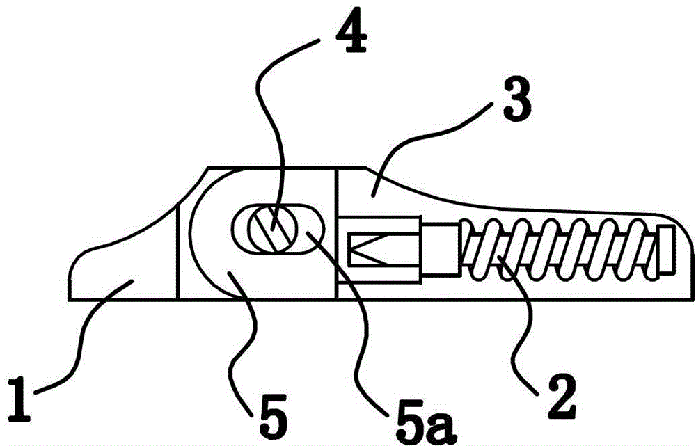
[0047] Such as Figure 4 As shown, the structure and principle of this embodiment are basically the same as that of Embodiment 1, the difference is that the number of single teeth 5 in this embodiment is one piece, and the inner surface of the single tooth 5 and the outer side of one side of the hinge head 1 Face to face.

Embodiment 3

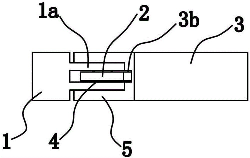
[0049] Such as Figure 5 As shown, the structure and principle of this embodiment are basically the same as those of Embodiment 1, except that each of the two single teeth 5 in this embodiment has a through hole 5a.


PUM


Abstract

The invention provides an elastic hinge of a pair of glasses, and belongs to the technical field of glass manufacturing. The problems that a conventional glass foot is poor in swinging-preventing effect and the like are solved. The elastic hinge of the glasses comprises a hinge head, a spring cylinder and a slingshot shell, wherein the spring cylinder is installed inside the slingshot shell. The hinge is characterized in that at least one sheet-shaped single tooth is arranged at the end surface of one end, having an installing hole, of the slingshot shell along the axial direction of the spring cylinder; at least one hinging sheet is arranged at the hinging part of the hinge head; a hinging end is arranged at the outer end of the spring cylinder and is hinged with the hinging sheet of the hinge head through a pin shaft; and the outer side plane of the hinge sheet is attached to the inner side plane of the single tooth. The elastic hinge of the glasses has the advantages of preventing the glasses foot from moving leftwards and rightwards, being high in fastness degree, good in stability and the like.

Description

technical field [0001] The invention belongs to the technical field of spectacles manufacturing, and relates to an elastic hinge for spectacles, in particular to an elastic hinge for spectacles that can prevent the legs of the glasses from swinging left and right. Background technique [0002] In the past, most of the glasses sold on the market were connected by hinge screws. The clamping force of the glasses connected by this hinge is weak, and the position of the glasses frame is fixed after the glasses feet are opened, and the glasses feet cannot be over Do not turn it too much, otherwise it will be easily damaged. [0003] In response to the existing problems, people have made improvements. Most of the existing spectacle legs and spectacle frames are connected by elastic hinges. For example, Chinese patent documents disclose elastic hinges for spectacle frames [Patent No.: 200820095445.2; Authorization Notice No.: CN201226057Y] , which includes hinged double teeth, a sl...

Claims


Application Information

Patent Timeline
Patent Type & Authority Patents(China)
IPC IPC(8): G02C5/22
Inventor 黄秉共
Owner 玉环市金富华眼镜科技股份有限公司
Why Eureka
Try Eureka