Stratified monitoring command system and cross-camera virtual tracking method

A command system and virtual tracking technology, applied in CCTV systems, components of TV systems, and image communication, etc., can solve the problems of distraction of monitoring personnel, easy tracking of targets across cameras, and fatigue when viewing multi-channel videos.

Active Publication Date: 2013-02-20
SHENZHEN INFINOVA
View PDF4 Cites 40 Cited by
  • Summary
  • Abstract
  • Description
  • Claims
  • Application Information

AI Technical Summary

Problems solved by technology

[0007] The purpose of the present invention is to provide a layered monitoring command system and a cross-camera virtual tracking method for targets, which aims to solve the problem of distraction of monitoring personnel due to frequent switching between multiple video images in the monitoring process of the existing monitoring system, and It is easy to get tired after watching multi-channel videos for a long time, and it is easy to lose track of the target across cameras during the monitoring process

Method used


Image

  • Stratified monitoring command system and cross-camera virtual tracking method
  • Stratified monitoring command system and cross-camera virtual tracking method
  • Stratified monitoring command system and cross-camera virtual tracking method

Examples


Embodiment 1

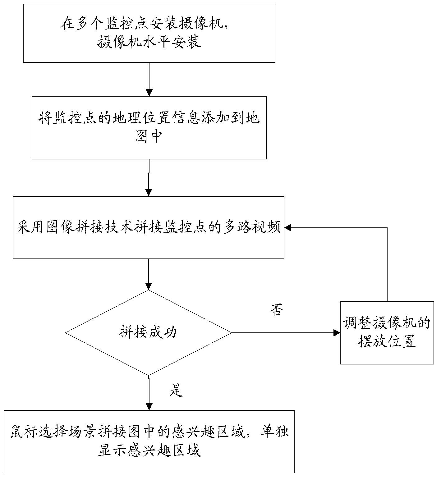
[0040] image 3 The implementation process of a monitoring system provided by Embodiment 1 of the present invention is shown, and the details are as follows:

[0041] During the camera installation process, the cameras at the same monitoring point are placed horizontally, and the overlapping area of ​​the camera shooting screen accounts for about 1 / 3 of the screen.

[0042] Add the geographic information of the monitoring point to the map, and click the monitoring point on the map to call the video information there.

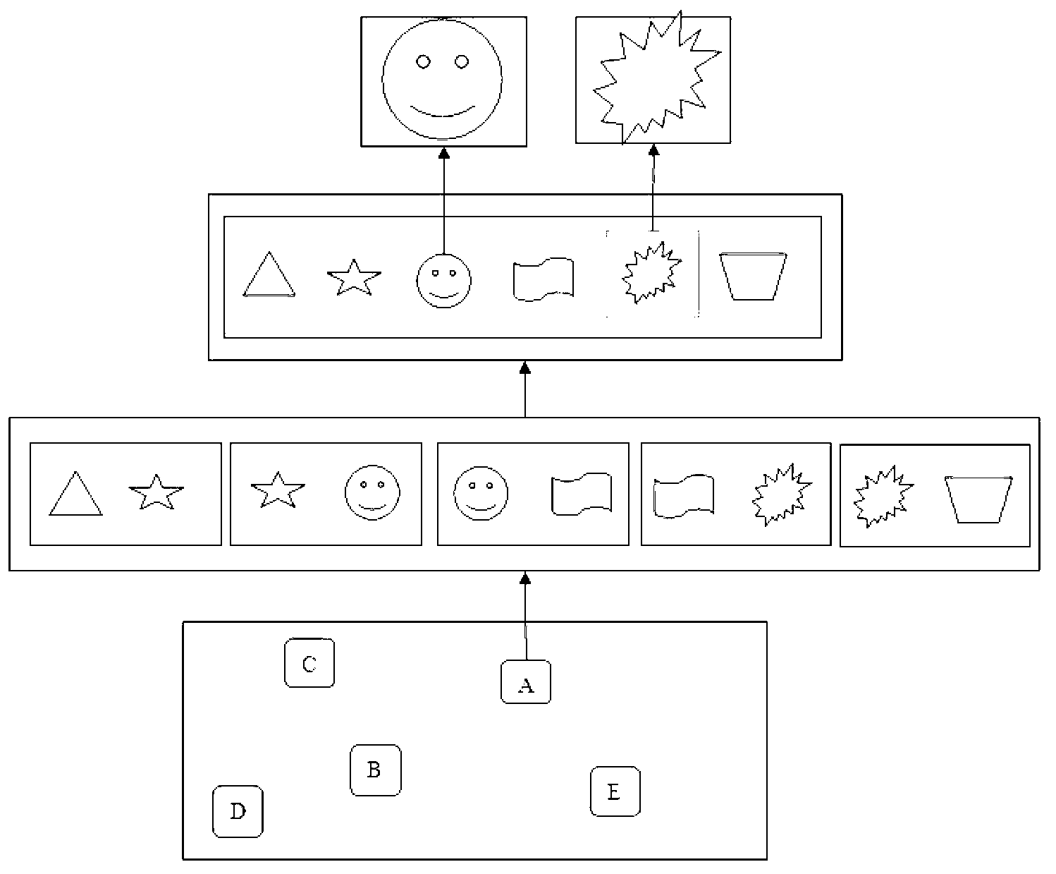
[0043] Using image stitching techniques, such as Figure 4 As shown, multiple videos are spliced ​​horizontally.

[0044] If the splicing is successful, display the spliced ​​scene graph; if the splicing fails, adjust the position of the camera, the focal length of the lens, etc.

[0045] The mouse selects a region of interest in the stitching scene, and by obtaining the mouse information, the image information of the mouse-selected rectangular region is disp...

Embodiment 2

[0048] Figure 5 The implementation flow of a monitoring system provided by Embodiment 2 of the present invention is shown, and the details are as follows:

[0049] During the camera installation process, the cameras at the same monitoring point are placed vertically, and the overlapping area of ​​the camera shooting screen accounts for about 1 / 3 of the screen.

[0050] Add the geographic information of the monitoring point to the map, and click the monitoring point on the map to call the video information there.

[0051] Using image stitching techniques, such as Figure 6 As shown, multiple videos are spliced ​​vertically.

[0052] If the splicing is successful, display the spliced ​​scene graph; if the splicing fails, adjust the position of the camera, the focal length of the lens, etc.

[0053]The mouse selects a region of interest in the stitching scene, and by obtaining the mouse information, the image information of the mouse-selected rectangular region is displayed s...

Embodiment 3

[0056] Figure 7 The implementation process of a monitoring system provided by Embodiment 3 of the present invention is shown, and the details are as follows:

[0057] During the camera installation process, the cameras at the same monitoring point are placed horizontally and vertically, and the overlapping area of ​​the camera shooting screen accounts for about 1 / 3 of the screen.

[0058] Add the geographic information of the monitoring point to the map, and click the monitoring point on the map to call the video information there.

[0059] Using image stitching techniques, such as Figure 8 As shown, multiple videos are spliced ​​horizontally and vertically.

[0060] If the splicing is successful, display the spliced ​​scene graph; if the splicing fails, adjust the position of the camera, the focal length of the lens, etc.

[0061] The mouse selects a region of interest in the stitching scene, and by obtaining the mouse information, the image information of the mouse-sele...


PUM


Abstract

The invention provides a stratified monitoring command system and a cross-camera virtual tracking method. The method comprises the following steps of: clicking a certain monitoring point A on an electronic map, displaying the scene mosaicked video obtained by multiple cameras installed at the monitoring point A, by mouse response, manually selecting an interested region from the mosaicked scene, or manually sliding the mouse to track the target, and displaying the information of the surrounding regions of the target, thereby realizing integral and local stratified monitoring on the monitored scene. In the method, the operation of switching back and forth among multiple video pictures is avoided, one integral and continuous monitoring picture is presented finally, and simultaneously, by mouse response, the monitoring workers participate in the video monitoring, the interested region and the motion target region are displayed in real time, the target is tracked manually by the mouse, and the cross-camera virtual tracking on the target is realized.

Description

technical field [0001] The invention belongs to the technical field of intelligent video processing, and in particular relates to a new video monitoring platform and a cross-camera virtual tracking method for a moving target. [0002] Background technique [0003] Today, with the rapid development of the monitoring system, the scale of the system is getting bigger and bigger, and there are more and more monitoring points. The staff have no time to take care of more and more monitoring images. With the continuous expansion of the monitoring range, it is necessary to monitor the entire bridge. , Airports, a long section of road or high-rise buildings are monitored, and the field of view of most cameras cannot reach such a large monitoring range. Therefore, the requirements for video surveillance with a large field of view are gradually increasing, and a high-end demand has gradually formed. As a solution, panoramic video stitching has also received more and more attention. T...

Claims


Application Information

Patent Timeline
Patent Type & Authority Applications(China)
IPC IPC(8): H04N5/262H04N5/14H04N7/18
Inventor 刘军魏园波赵金桃
Owner SHENZHEN INFINOVA
Why Eureka
Try Eureka