lubricant distributor

A lubricating oil distributor and lubricating oil technology, applied in the direction of distribution devices, lubricating parts, engine lubrication, etc., can solve the problems of high cost, monitoring pipeline rupture, etc.

Inactive Publication Date: 2016-03-16
BAIER & KOPPEL GMBH & CO
View PDF7 Cites 0 Cited by
  • Summary
  • Abstract
  • Description
  • Claims
  • Application Information

AI Technical Summary

Problems solved by technology

However, this solution for monitoring line breaks has the disadvantage t

Method used


Image

  • lubricant distributor
  • lubricant distributor
  • lubricant distributor

Examples


Embodiment Construction

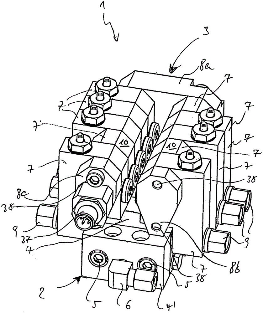
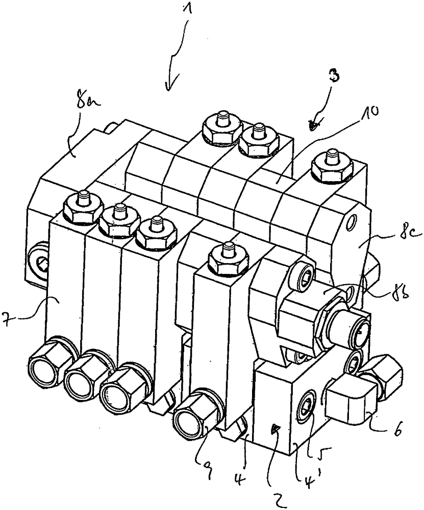
[0023] attached figure 1 A perspective view of the lubricating oil distributor 1 of the present invention is shown. The lubricating oil distributor 1 includes a main distributor 2 and a pipeline rupture monitor 3 . The main dispenser 2 can be, for example, a known progressive dispenser, but in principle the main dispenser 2 can have any desired configuration. The main distributor 2 includes a plurality of distributor outlets, which are not shown in this figure, and the fluid (especially lubricating oil) is transported from these distributor outlets to the positions requiring lubricating oil through corresponding pipelines. The tubing is also not shown in this figure.

[0024] in the attached figure 1 Among them, as an example only, the main distributor 2 has a modular construction, that is to say, the main distributor 2 includes a plurality of main distributor modules 4, which are connected to each other by connecting parts 5 (especially connected by hexagon socket head bo...


PUM


Abstract

The invention relates to a lubricant distributor (1), in particular for use in central lubricating systems for machines, vehicles, construction machines, or agricultural machines, for conveying and distributing lubricant from a lubricant source to predetermined lubricant discharge points by means of one or more lines,comprising a main distributor (2). The lubricant distributor is characterized in that the lubricant distributor comprises at least one line-break monitor (3) for detecting a pressure drop in at least one line, and in that the at least one line-break monitor (3) is structurally arranged in or on the main distributor (2) in order to create a rigid unit comprising the main distributor (2) and the line-break monitor (3).

Description

technical field [0001] The invention relates to a lubricating oil distributor, especially a lubricating oil distributor used in a centralized lubricating system for machines, vehicles, construction equipment or agricultural equipment. The oil source is conveyed and distributed to pre-set lubricant supply points. Background technique [0002] Centralized lubrication systems often encounter a problem, that is, due to the many branches of the oil pipeline network, it is often difficult to determine whether there is a rupture in the oil pipeline or to locate the location of the rupture. In centralized lubrication systems with one or more progressive distributors, the problem may also arise that in the event of a rupture in the line downstream of the progressive distributor, due to the The pressure drop of the metering plunger interrupts the continuous (gradual) push action of the metering plunger, so that the lubricating oil backflows, so that the lubricating oil can no longer ...

Claims


Application Information

Patent Timeline
IPC IPC(8): F16N29/04F16N25/00F16N7/38
CPCF16N29/04F16N7/385F16N25/00F16N2260/08F16N2260/12F16N2260/22
Inventor 于尔根·布伦德尔
Owner BAIER & KOPPEL GMBH & CO
Why Eureka
Try Eureka