Battery block

a battery and block technology, applied in the field of batteries, can solve the problems of high-temperature and high-pressure gas not being able to be quickly exhausted, and inner gas cannot be quickly exhausted

Active Publication Date: 2019-07-04
SANYO ELECTRIC CO LTD
View PDF2 Cites 16 Cited by
  • Summary
  • Abstract
  • Description
  • Claims
  • Application Information

AI Technical Summary

Benefits of technology

[0010]Solution to Problem and Advantageous Effects of Invention
[0013]lead plates (3) which are connected to the electrodes (15) of the cylindrical batteries (1).
[0014]The cylindrical batteries (1) are provided with battery cans (10) having bottom plates (12) provided with bottom surface electrodes (15B) and exhaust valves (16). The exhaust valves (16) which are provided in the bottom plates (12) open as a result of thin-walled lines (17) breaking at a threshold pressure.
[0015]The exhaust valves (16) are provided inside the loop-shaped thin-walled lines (17) provided in the bottom plates (12), said thin-walled lines having unconnected portions (19).
[0016]The unconnected portions (19) form hinge parts (25).
[0017]Furthermore, the bottom surface electrodes (15B) provided in the bottom plates (12) connect the lead plate to the hinge parts (25).

Problems solved by technology

Therefore, there is a trouble that the high-temperature and high-pressure gas cannot be exhausted quickly.
Then, the inner gas cannot be quickly exhausted.
Therefore, there is a fault that the inner gas cannot be quickly exhausted with both of exhaust valves 93 opened widely.

Method used


Image

  • Battery block
  • Battery block
  • Battery block

Examples


Embodiment Construction

[0043]Exemplary embodiments and examples of the present invention have been described with reference to the drawings. However, the exemplary embodiment described below shows a battery block for embodying the technical ideas of the present invention. The battery block of the present invention is not limited to the following. Further, in the present description, components shown in the scope of claims are not limited to the components of the exemplary embodiment.

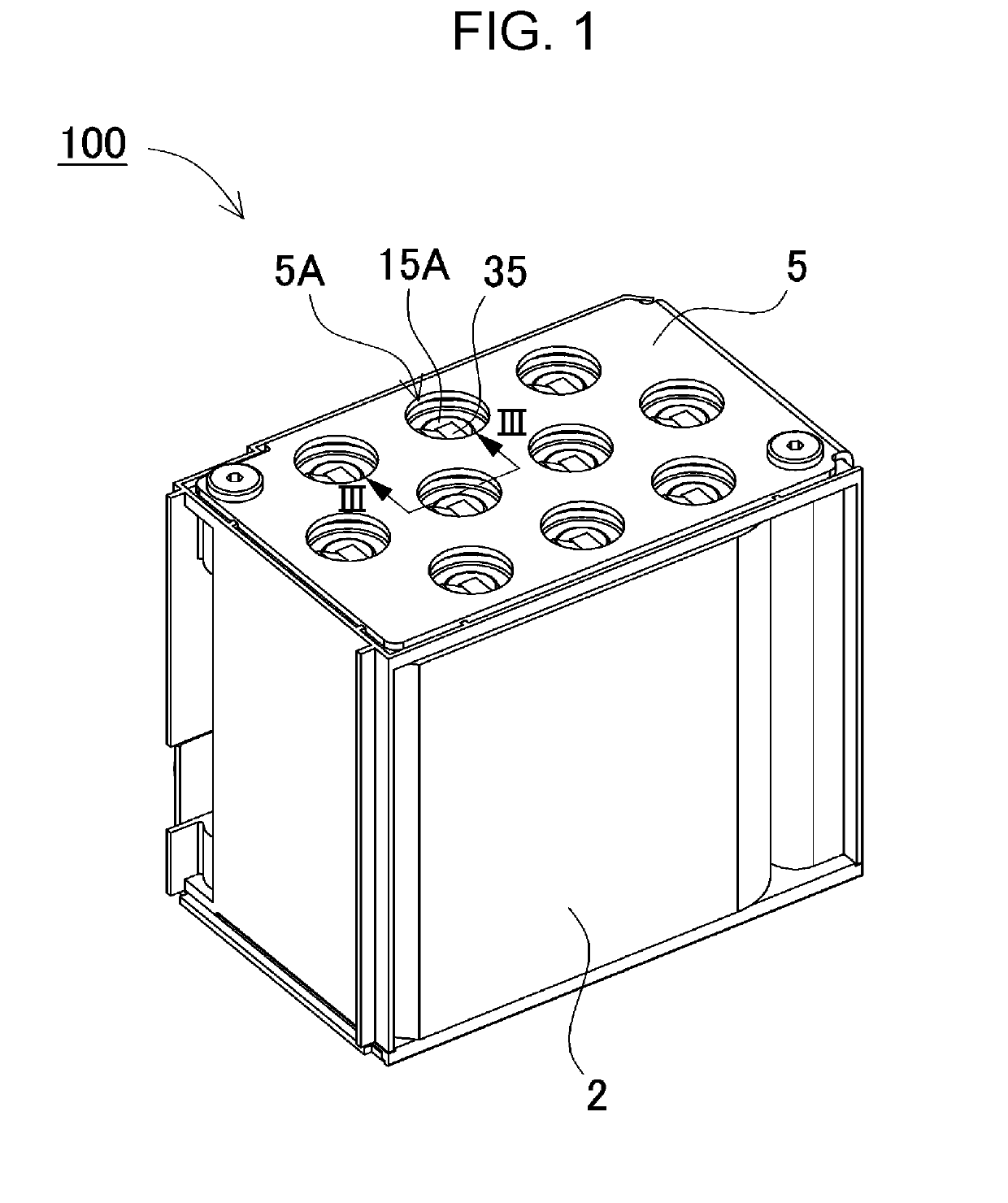
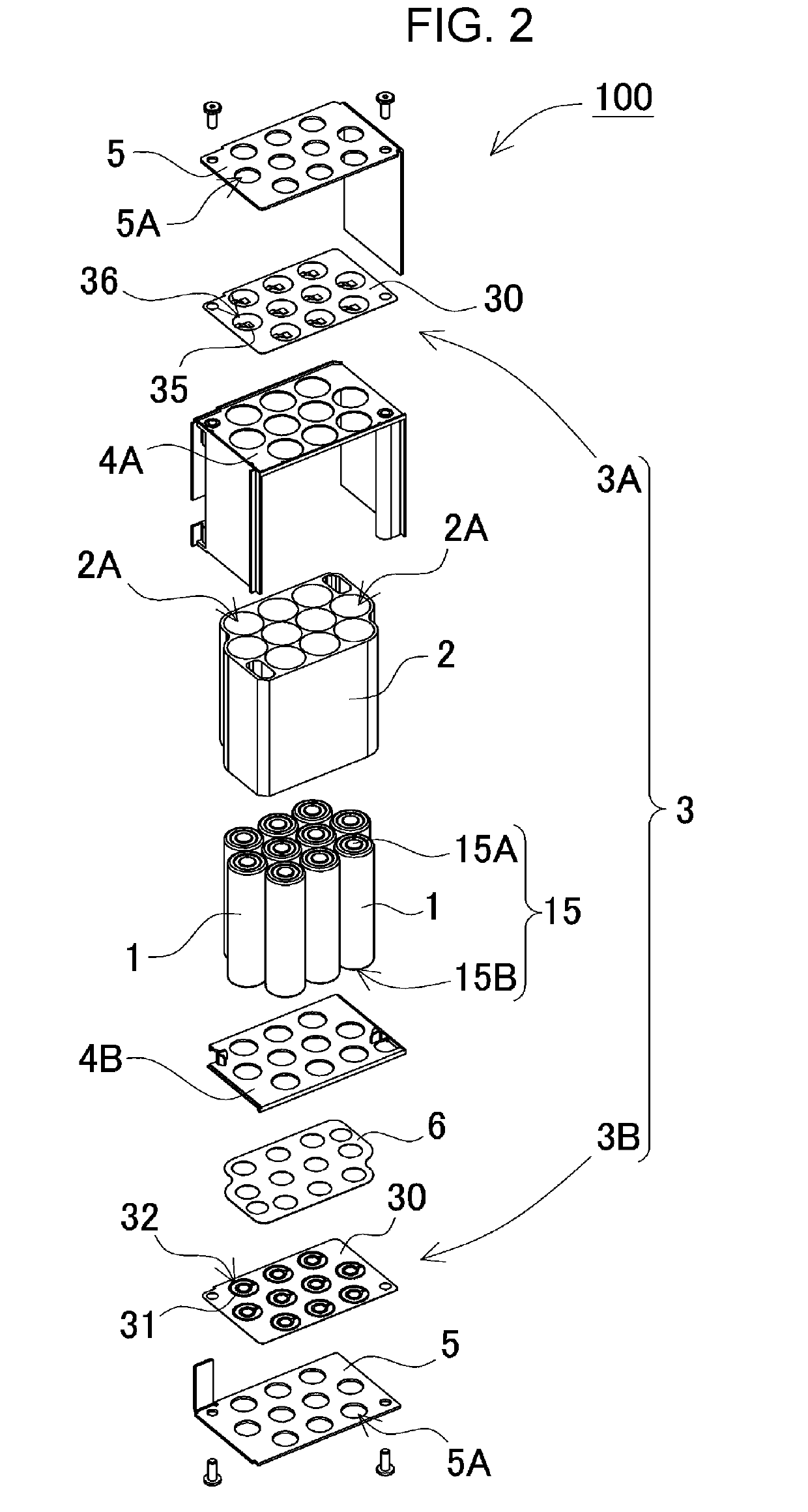
[0044]Battery block 100 shown in FIGS. 1 and 2, includes a plurality of cylindrical batteries 1. In battery block 100, the current can be enlarged by connecting cylindrical batteries 1 in parallel, and the output voltage can be increased by connecting cylindrical batteries 1 in series. The charge and discharge capacity can be enlarged by increasing the number of connected cylindrical batteries 1. Therefore, in battery block 100, the plurality of cylindrical batteries 1 are connected in series or parallel, in order to obtain th...


PUM

PropertyMeasurementUnit
thicknessaaaaaaaaaa
lengthaaaaaaaaaa
diameteraaaaaaaaaa

Abstract

A battery block is provided with: a plurality of cylindrical batteries of each of which the two ends are formed as positive and negative electrodes; and a lead plate which is connected to the electrodes of the cylindrical batteries. The cylindrical batteries are provided with battery cans having bottom plates provided with bottom surface electrodes and exhaust valves. The exhaust valves which are provided in the bottom plates open as a result of thin-walled lines breaking at a threshold pressure. The exhaust valves are provided inside the loop-shaped thin-walled lines provided in the bottom plates, said thin-walled lines having unconnected portions. The unconnected portions form hinge parts. Furthermore, the bottom surface electrodes provided in the bottom plates connect the lead plate to the hinge parts. The lead plate has cut-out portions provided in positions facing areas including the thin-walled lines.

Description

TECHNICAL FIELD[0001]The present invention relates to a battery block in which a plurality of cylindrical batteries are connected by a lead plate. Especially the present invention relates to the battery block described in the following. In this battery block, cylindrical batteries are connected by a lead plate. These cylindrical batteries each have an exhaust valve which breaks when the inner pressure increases abnormally.BACKGROUND ART[0002]In a battery block which provides power to a driving motor of a hybrid car or an electric vehicle, the output and the charge and discharge capacity are enlarged by connecting a lot of secondary batteries in series or parallel. In order that this type of the battery block realizes or secures a high safety, the battery block is provided with an exhaust valve. This exhaust valve prevents harmful effects by rupture of the battery can. Since the exhaust valve opens when the inner pressure becomes higher than a threshold pressure, the rupture of the b...

Claims


Application Information

Patent Timeline
Patent Type & Authority Applications(United States)
IPC IPC(8): H01M2/12H01M2/26H01M2/10H01M50/213H01M50/503H01M50/516H01M50/522H01M50/533H01M50/534
CPCH01M2/1241H01M2/26H01M2/1077H01M2200/20H01M2220/20Y02E60/10H01M50/3425H01M50/522H01M50/213H01M50/516H01M50/534H01M50/503H01M50/533
Inventor KOUTARI, MASATOEGASHIRA, TAKUYATAKATA, HIROSHIYASUI, SHUNSUKE
Owner SANYO ELECTRIC CO LTD
Why Eureka
Try Eureka