
Automatic code page laying machine

A code page, automatic technology, applied in the field of automatic code page placement machine, to achieve the effect of smooth fabric and labor saving

Active Publication Date: 2015-09-30
临沂高新人才教育发展集团有限公司
View PDF13 Cites 0 Cited by
  • Summary
  • Abstract
  • Description
  • Claims
  • Application Information

AI Technical Summary

Problems solved by technology

[0004] Purpose of the invention: The present invention aims at the defect of wind shrinkage in the existing manual laying, and provides a high-efficiency automatic code page laying machine

Method used

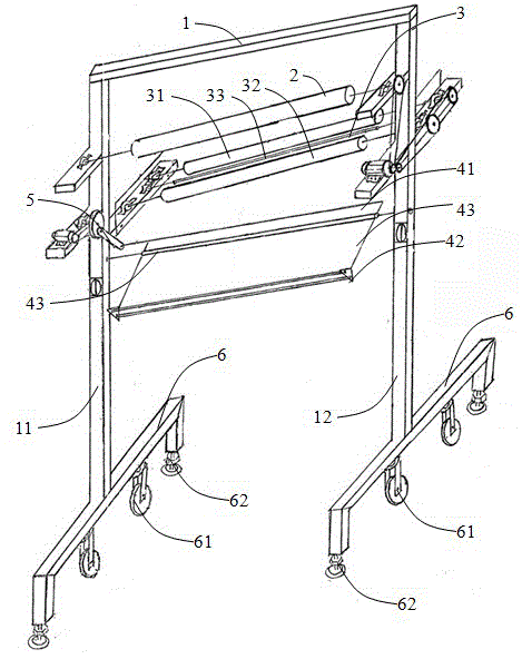

Image

  • Automatic code page laying machine

Examples


Embodiment Construction

[0010] Below in conjunction with accompanying drawing and specific embodiment, further illustrate the present invention, should be understood that these embodiments are only for illustrating the present invention and are not intended to limit the scope of the present invention, after having read the present invention, those skilled in the art will understand various aspects of the present invention Modifications in equivalent forms all fall within the scope defined by the appended claims of this application.

[0011] see figure 1 As shown, the automatic code page laying machine of the present invention, an automatic code page laying machine, includes a main frame 1, a transmission wheel 2, a driving wheel 3 and a swing rod 4. The main frame 1 includes a first upright pole 11 and a second upright pole 12 arranged in parallel. Wherein, the first upright rod 11 and the second upright rod 12 are square tube flat tubes. Wherein, the driving wheel 3 is arranged below the transmiss...


PUM


Abstract

The invention discloses an automatic cloth stacking and unrolling machine which comprises a main frame, a transmission wheel, a driving wheel and a swing rod. The main frame comprises a first upright column and a second upright column, which are arranged in parallel to each other; a first support is arranged on one side of the main frame; the transmission wheel is arranged on the first support, a second support is arranged on the other side of the main frame; the driving wheel is arranged on the second support; the driving wheel comprises a first wheel shaft and a second wheel shaft, which are arranged in parallel to each other; a bottom rod is arranged between the first and the second wheel shafts; the swing rod comprises an upper swing unit, a lower swing unit, a flat plate and a hollow tube; the flat plate is connected with the upper and the lower swing units; the lower swing unit comprises a first lower swing tube and a second lower swing tube, which are arranged in parallel to each other. A cloth roll is unrolled under a frictional force generated by the synchronous rotation of the two wheels, and the cloth is stacked based on the lever principle. The automatic cloth stacking and unrolling machine solves the difficulty of unrolling and air-shrinkage during the cutting and tailing process in the clothes industry, so as to achieve the labor-saving effect; and keeps the cloth flat and smooth and avoids the problem that the cloth is wrinkled and wasted during the manual cloth-unrolling process, so as to achieve the effect of cloth conservation.

Description

technical field [0001] The invention belongs to the field of cutting in the garment industry, and in particular relates to an automatic code page laying machine. Background technique [0002] For the convenience of transportation, the cloth factory currently packs all kinds of fabrics into rolls for delivery, which brings the phenomenon of fabric shrinkage to the production of the garment factory, and the cut pieces cannot reach the predetermined size. In order to solve this problem, the factory manually releases the cloth to give the wind shrinkage, which is characterized by slow speed, the laid down cloth is messy, and leaves a lot of fold marks, which is not conducive to the mesh. When the mesh is clothed, it cannot be flattened, resulting in increased loss. [0003] Therefore, need a kind of new automatic page laying machine to solve the above problems. Contents of the invention [0004] Purpose of the invention: The present invention provides a high-efficiency auto...

Claims


Application Information

Patent Timeline
Patent Type & Authority Patents(China)
IPC IPC(8): B65H45/107
Inventor 刘尚斌张国际张玉顺曹本胜
Owner 临沂高新人才教育发展集团有限公司
Learn More