
Novel motor

A new type of motor housing technology, applied in electrical components, electromechanical devices, magnetic circuit static parts, etc., can solve the problems of large starting current, large power consumption, and high use cost, and achieve reduced starting current and extended use. Longevity, improve the effect of interaction

Inactive Publication Date: 2013-02-27
王九龙
View PDF0 Cites 6 Cited by
  • Summary
  • Abstract
  • Description
  • Claims
  • Application Information

AI Technical Summary

Problems solved by technology

[0002] Various existing motors, such as AC induction motors, have simple structure and reliable operation, but they have difficulties in starting, large starting current, large power consumption, high calorific value, low efficiency, and difficulty in speed regulation.
Existing brushed and brushless DC motors include permanent magnet DC motors. Although they have higher working efficiency and easier speed regulation than the former, they have high calorific value, high cost, high failure rate, easy burning, difficult maintenance, and permanent magnet energy utilization. Low rate, large rotor inertia
[0003] The existing generators also have common disadvantages, that is, the motor is prone to heat, low efficiency, low utilization rate of permanent magnet energy, and high cost of use

Method used


Image

  • Novel motor
  • Novel motor
  • Novel motor

Examples


Embodiment Construction

[0030] The present invention will be further described below in conjunction with the accompanying drawings.

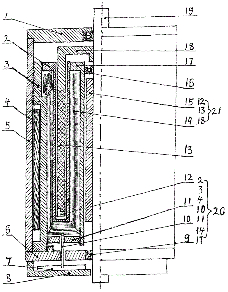
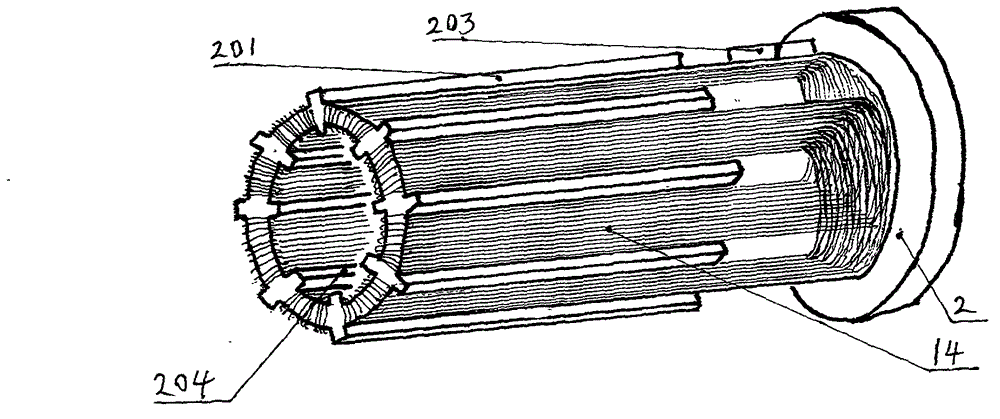
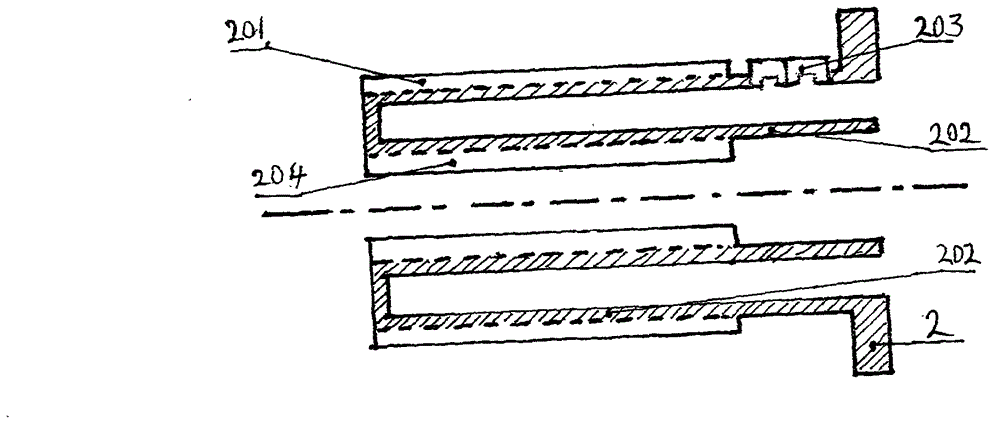
[0031] See attached figure 1 to attach Figure 12 As shown, a new type of motor includes; 20. The cup-shaped rotor 21 is equipped with a front end cover 1 and a rear end cover 6 on both sides of the motor casing 5, and a bearing 9 is arranged at the center of the front end cover 1 and the rear end cover 6, and the two ends of the motor shaft 19 pass through the bearing 9 and the front end cover. The cover 1 is connected to the rear end cover 6, and one end of the magnetic sleeve 15, the stator inner sleeve bearing 16 and the cup-shaped rotor 21 are respectively connected with the motor shaft 19, the stator 20 is arranged in the motor casing 5, and one end of the stator 20 is connected to the rear end The covers 6 are connected concentrically. The cup-shaped rotor 21 includes: permanent magnets 13, rotor brackets 18 and rotor end plates 12, and multiple pairs of circ...


PUM


Abstract

The invention provides a novel motor which comprise a motor casing, a stator and a cup-shaped rotor. The novel motor is characterized in that the cup-shaped rotor is provided with a magnetized multi-pole permanent magnet which is arranged on the cup-shaped cylinder wall; and the stator is provided with a stator outer sleeve which is arranged in a magnetic conductive cylinder, a coil skeleton is arranged in a stator inner sleeve, a plurality of groups of hollow coils are configured on the coil skeleton, the coils are configured at intervals, that is, the coils are arranged opposite to the inner peripheral surface of the permanent magnet and opposite to the outer peripheral surface of the permanent magnet simultaneously. The novel motor has the advantages that stator and rotor structures of a traditional motor are changed, and interaction of the coils with the permanent magnet is improved greatly by optimizing magnetic field distribution on coil tracks, accordingly, the motor efficiency is improved greatly, the starting current is reduced, and the power consumption is decreased. The stator coils are hollow coils, iron losses are decreased, the motor weight is lightened, the slot effect is removed, and the motor temperature rising is decreased simultaneously.

Description

technical field [0001] The invention belongs to the field of motors and relates to a permanent magnet motor / generator. Background technique [0002] Existing various motors, such as AC induction motors, have simple structure and reliable operation, but they have difficulty in starting, large starting current, large power consumption, high calorific value, low efficiency, and difficulty in speed regulation. Existing brushed and brushless DC motors include permanent magnet DC motors. Although they have higher working efficiency and easier speed regulation than the former, they have high calorific value, high cost, high failure rate, easy burning, difficult maintenance, and permanent magnet energy utilization. The rate is low and the rotor inertia is large. [0003] The existing generators also have common disadvantages, that is, the motor is prone to heat, low efficiency, low utilization rate of permanent magnet energy, and high cost of use. Contents of the invention [00...

Claims


Application Information

Patent Timeline
IPC IPC(8): H02K29/00H02K29/06H02K1/27H02K1/12
Inventor 王九龙
Owner 王九龙
Learn More