Method and system for enhancing demodulation reference signals

A technology for demodulating reference signals and signaling, applied in the field of enhancement methods and systems for demodulating reference signals, can solve problems such as limiting cell splitting gain, and achieve the effects of improving channel estimation accuracy, reducing interference, and improving spectral efficiency

Inactive Publication Date: 2013-03-06
ZTE CORP
View PDF4 Cites 52 Cited by
  • Summary
  • Abstract
  • Description
  • Claims
  • Application Information

AI Technical Summary

Problems solved by technology

Based on the DCI format 2C corresponding to mode 9, only two layers of orthogonal transmission can be realized between two nodes, that is, when ea

Method used


Image

  • Method and system for enhancing demodulation reference signals
  • Method and system for enhancing demodulation reference signals
  • Method and system for enhancing demodulation reference signals

Examples


Example Embodiment

[0071] Example 1:

[0072] In this embodiment, n-bit indication information is configured in the RRC signaling to indicate the demodulation reference signal port restriction information. Combining the ports indicated in DCI format 2C and unrestricted ports in RRC signaling, take the intersection of the ports indicated in the above two kinds of information to obtain the final port actually used, where the demodulation reference signal overhead is determined by DCI format 2C The indicated port is OK.

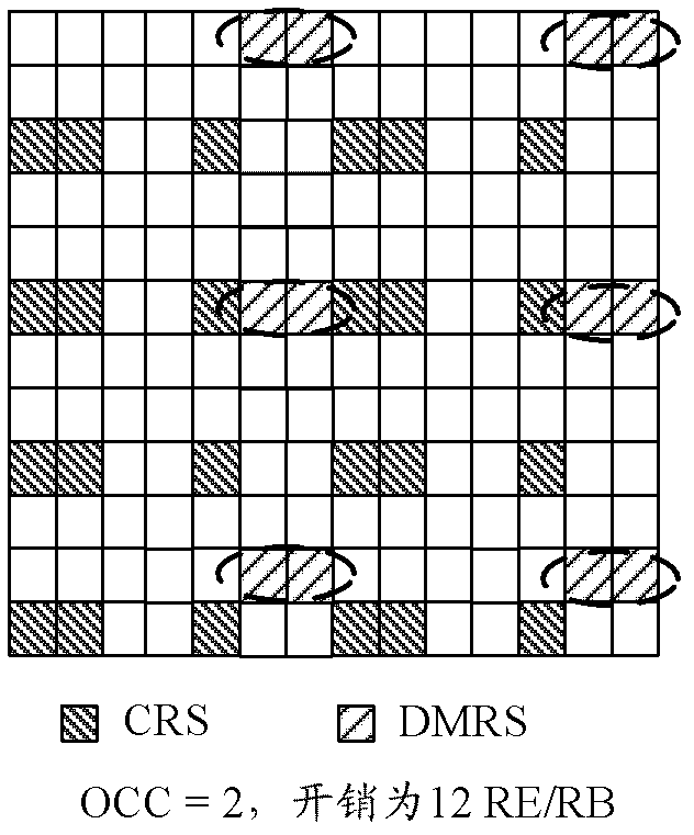
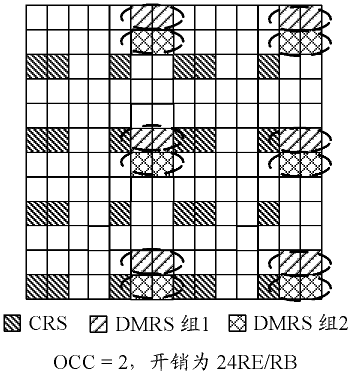
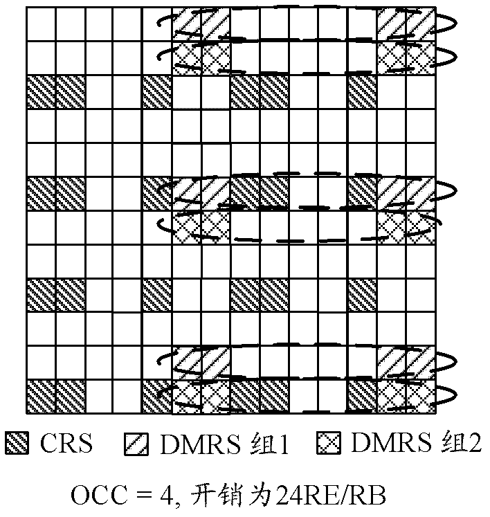
[0073] To facilitate understanding, combine figure 2 A specific embodiment is given, and the demodulation reference signal pattern shown in FIG. 1 is used as a reference description. in figure 2 Suppose there are two users occupying the same time-frequency resource for data transmission, and the rank used by each user for transmission is 2 (in the embodiment, the first transmission is used as an example, but the actual scenario is not limited to this). In addition, in the RRC signa...

Example Embodiment

[0080] Example 2:

[0081] In this embodiment, n-bit indication information is configured in the RRC signaling to indicate the type and / or overhead information of the demodulation reference signal port notified in the DCIformat. The demodulation reference signal types include physical demodulation reference signal port types and virtual demodulation reference signal port types.

[0082] When configured as a physical demodulation reference signal port type, the demodulation reference signal port notified in the DCI format is consistent with the demodulation reference signal port defined in LTE R10, that is, one-to-one correspondence; when configured as a virtual demodulation reference signal port type There is a specific mapping relationship between the demodulation reference signal port notified in the DCI format and the demodulation reference signal port defined in LTE R10, and the mapping relationship is transparent to the UE.

[0083] For example, use p-port(k) to represent the d...


PUM


Abstract

The invention discloses a method and a system for enhancing demodulation reference signals. By the method and the system, instruction information can be added into high-level RRC (radio resource control) signals. The method further includes jointly determining a service mode of each demodulation reference signal port by combining a LTE (long-term revolution) R10DCI (downlink control information) format with the instruction information added into the high-level RRC signals. The method and the system have the advantages that owing to the technology for enhancing the demodulation reference signals, orthogonal or quasi-orthogonal configuration among demodulation reference signal ports of different users can be realized flexibly without increasing complexity of UE (user equipment) on the basis that backward compatibility of the DCI format is guaranteed, accordingly, the spectral efficiency of a cell can be effectively improved, particularly, interference generated in an MU-MIMO (multiple user multiple-input multiple output) scene or a CoMP (coordinated multiple point transmission and reception) scene can be effectively reduced, the channel estimation precision is improved, and the spectral efficiency is enhanced.

Description

technical field [0001] The present invention relates to the communication field, in particular to a demodulation reference signal enhancement method and system. Background technique [0002] In wireless communication technology, when base stations such as evolved Node B (eNB) use multiple antennas to transmit data, spatial multiplexing can be used to increase the data transmission rate, that is, the same time-frequency resources are used at the transmitting end to transmit data on different antennas. The location transmits different data, and the receiving end such as user equipment (UE) also uses multiple antennas to receive data. [0003] In the case of a single user, the resources of all antennas are allocated to the same user, and this user exclusively occupies the physical resources allocated by the base station side within a transmission interval. This transmission method is called Single User Multiple-Input Input Multiple-Out-put, SU-MIMO); in the case of multiple us...

Claims


Application Information

Patent Timeline
IPC IPC(8): H04B7/08H04L1/00H04L27/26
Inventor 孙云锋郑勇郭森宝陈艺戬张峻峰
Owner ZTE CORP
Why Eureka
Try Eureka