Optical coupled resonator structures based on loop-coupled cavities and loop coupling phase

a resonator and cavity technology, applied in the field of optical resonator structures, can solve the problems of direct coupling between the first and second waveguides, which may or may not be substantially negligible, and achieve the effect of reducing the size and weight of the payload and high spectral efficiency

Inactive Publication Date: 2008-11-06
MASSACHUSETTS INST OF TECH
View PDF11 Cites 64 Cited by
  • Summary
  • Abstract
  • Description
  • Claims
  • Application Information

AI Technical Summary

Benefits of technology

[0008]In one embodiment, the structures of the present invention, which include at least an input port and a drop port, enable the design of spectral responses with transmission zeros in the drop port (at real and complex frequency detunings from resonance). This enables optimally sharp filter responses (using real-frequency zeros), and dispersion-engineered spectral responses (using complex-frequency zeros). The latter responses are non-minimum-phase and therefore are not subject to the well known Kramers-Kronig (Hilbert transform) constraint between the amplitude and phase spectral responses. In particular, the structures of the present invention permit the design of spectral responses with passbands having a flat-top amplitude response at the same time as a nearly linear phase response, without the need for additional dispersion compensation following the structure (e.g., by all-pass filters). Such responses are optimal, in the sense that a minimum number of resonant cavities are used for a given amplitude response selectivity and phase linearity.
[0009]Applications of the disclosed structures include: i) channel add-drop filters for high spectral efficiency photonic networks for telecommunication applications as well as for intrachip photonic networks for next-generation microprocessors; ii) dispersion-compensated filters; iii) slow-wave resonator-based structures for sensors, channelized modulators, amplifiers, wavelength converters, and coupled-cavity nonlinear optics in general. Another example application is in microwave photonics, where the flat-top, linear-phase microphotonic filters may be used in combination with an optical modulator to replace microwave satellite transponder filters, thereby reducing the size and weight of the payload. The flat-top, linear-phase microphotonic filters may also be used in terrestrial microwave filtering, such as in spectral slicing filters in cellular telephone towers.

Problems solved by technology

However, the direct coupling between the first and second waveguides may or may not be substantially negligible, as dictated by the particular design.

Method used


Image

  • Optical coupled resonator structures based on loop-coupled cavities and loop coupling phase
  • Optical coupled resonator structures based on loop-coupled cavities and loop coupling phase
  • Optical coupled resonator structures based on loop-coupled cavities and loop coupling phase

Examples


Embodiment Construction

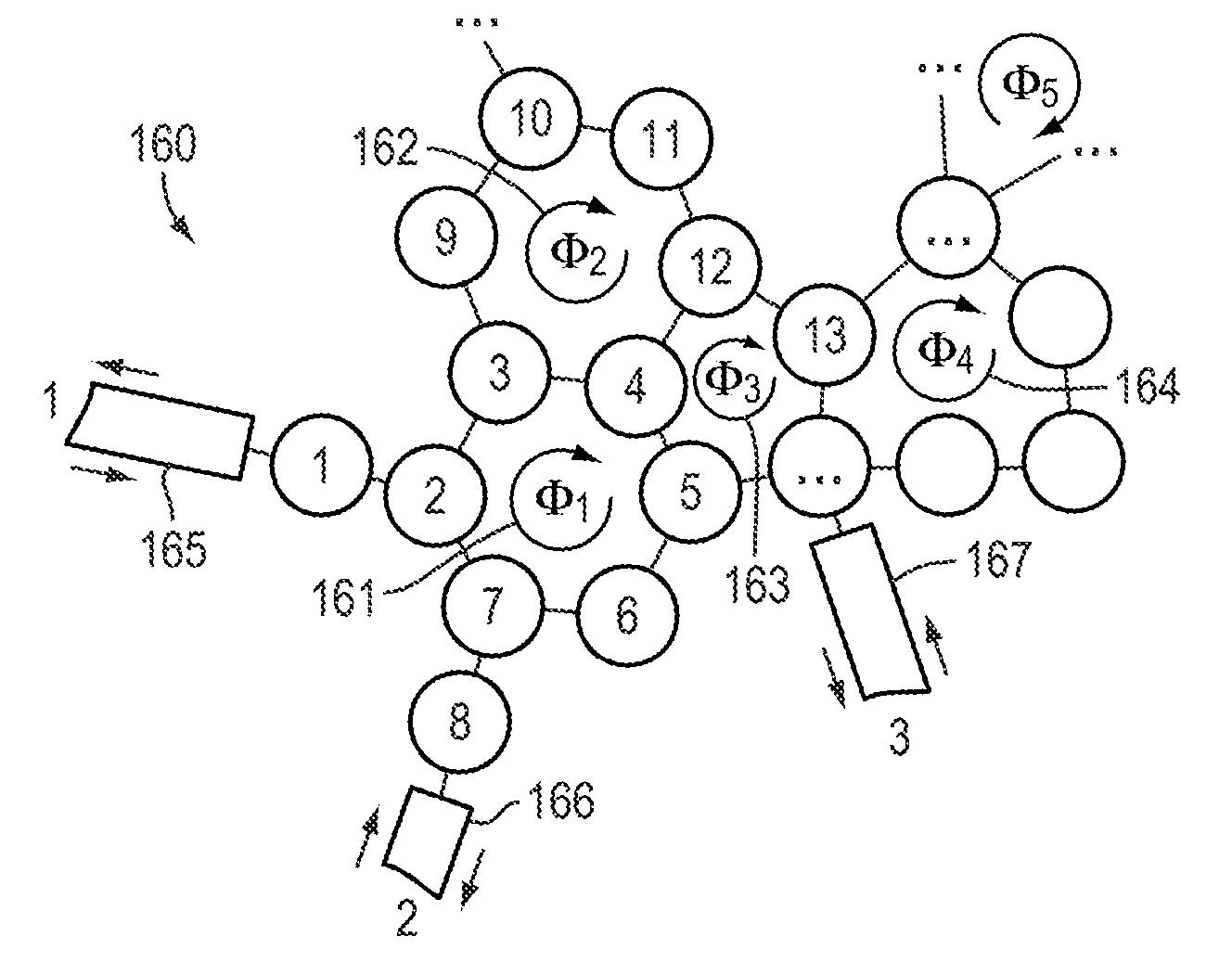
[0066]In general, the present invention pertains to optical-coupled resonator structures that are based on loop-coupled cavities and loop coupling phase.

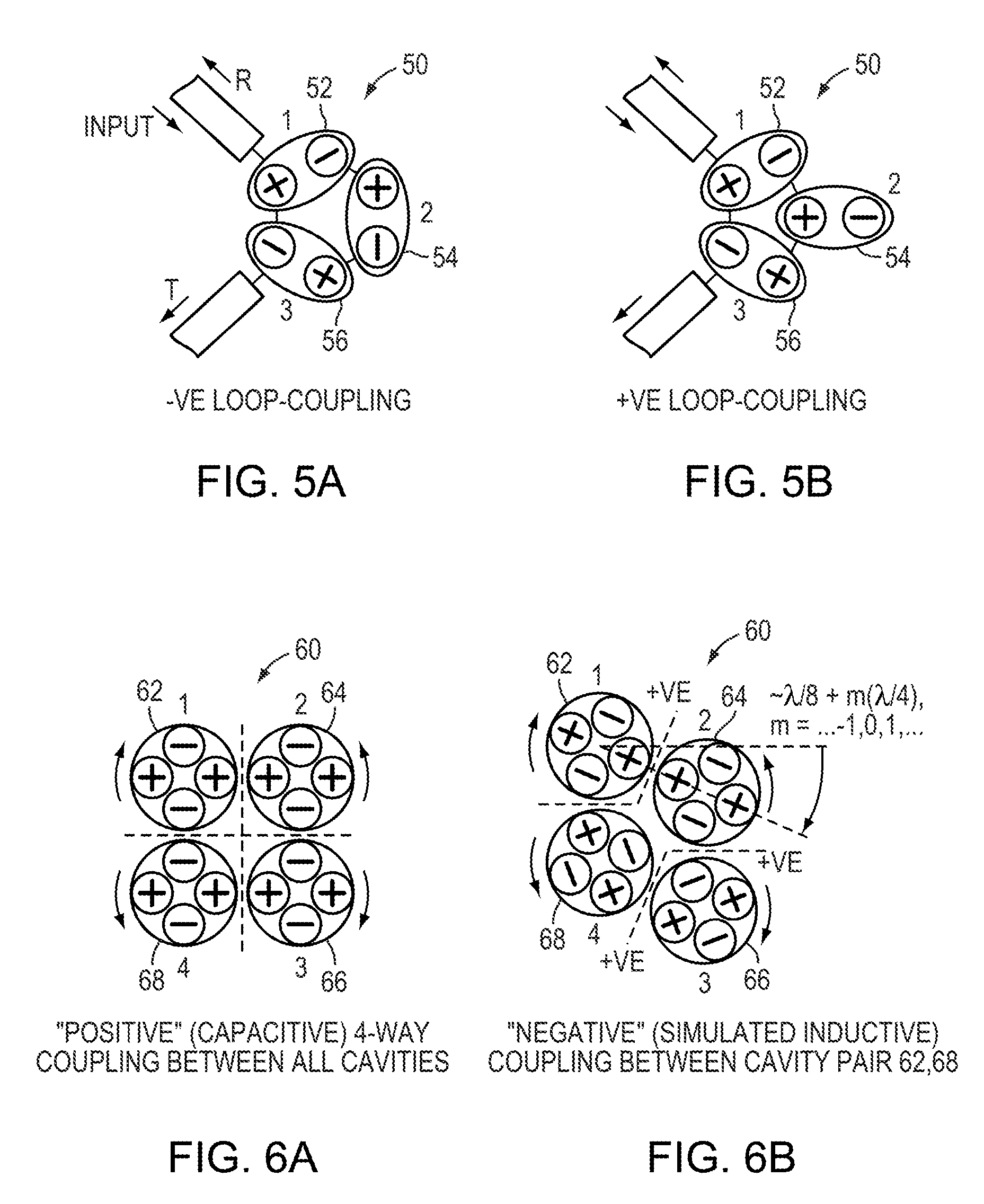
[0067]Loop coupling of cavities may be understood as follows. FIGS. 5a-b each show one embodiment of a third-order loop-coupled resonant structure 50 (i.e., a resonant structure having three cavities or, more rigorously, three resonant modes in use near the wavelength of interest, which may or may not be substantially located in separate cavities), based on standing wave cavities. The structure 50 includes a single coupling loop. A (non-trivial) coupling loop is defined as a path through a sequence of mutually coupled cavities that begins with an arbitrary cavity and that ends at that same arbitrary cavity after traversing at least two other cavities, but without the path being retraced. For example, the coupling loop of FIGS. 5a and 5b can be written as the sequence 52-54-56-52, with numbers referring to the cavities. Sequences rep...


PUM


Abstract

A resonator structure includes an input waveguide and an output waveguide. In one embodiment, the resonator structure also includes at least one resonator that couples the input waveguide to the output waveguide and a directional coupler that optically couples the input waveguide to the output waveguide. In another embodiment, the resonator structure includes a plurality of ring resonators that couple the input waveguide to the output waveguide. The plurality of ring resonators include a sequence of ring resonators that form a coupling loop. Each ring resonator in the sequence is coupled to at least two other ring resonators in the sequence and the first ring resonator in the sequence is coupled to the last ring resonator in the sequence so as to form the coupling loop.

Description

TECHNICAL FIELD[0001]The invention generally relates to optical resonator structures. More particularly, the invention relates to integrated optical (microphotonic) resonant structures that comprise loop-coupled cavities having an associated loop coupling phase, and may include, for example, microring resonators, photonic crystal microcavities, and standing wave dielectric resonators.BACKGROUND[0002]Coupled resonators have previously been used in optics, and particularly in integrated optics, for the design of various amplitude and phase filtering structures. Previous work on coupled-cavity resonant structures includes: series-coupled-cavity (SCC) structures (FIG. 1), parallel-coupled-cavity (PCC) filters (FIG. 2), and Mach-Zehnder all-pass decomposition (AD) resonant structures (FIG. 3).[0003]Series-coupled-cavity structures (also referred to as coupled-resonator optical waveguides—CROWs—in slow-light literature), such as the structure 310 shown in FIG. 1, may be used as channel ad...

Claims


Application Information

Patent Timeline
Patent Type & Authority Applications(United States)
IPC IPC(8): G02B6/26
CPCG02B6/12007G02B6/29343
Inventor POPOVIC, MILOS
Owner MASSACHUSETTS INST OF TECH
Why Eureka
Try Eureka