Fixing structure of radiating element

A technology of fixed structure and heat dissipation components, applied in the direction of electrical components, electric solid devices, semiconductor devices, etc., can solve the problems of reduced heat transfer efficiency, loss of air tightness, easy generation of thermal resistance, etc., to avoid thermal resistance. phenomenon, long service life, increase the effect of tight fit

Active Publication Date: 2013-03-06
ASIA VITAL COMPONENTS SHENZHEN CO LTD
View PDF3 Cites 0 Cited by
  • Summary
  • Abstract
  • Description
  • Claims
  • Application Information

AI Technical Summary

Problems solved by technology

[0006] It is known that the vapor chamber is used in combination with a substrate and conducts the heat of the heating element on the substrate through the vapor chamber. The known technology is mainly in the position where the vapor chamber avoids the chamber, that is, the four couplings of the vapor chamber. A copper column with internal screw teeth is perforated at each place, and at least one hole is opened on the base plate relative to the position of the copper column on the uniform temperature plate, and then the copper column and the hole are simultaneously threaded through a screw locking element in a screw-locked manner The vapor chamber is fixed on the base plate, but because the copper pillars are installed at the four couplings of the chamber, the distance between the chamber and the heating element is far away, and the chamber cannot be closely attached to the heating element after being fixed. In order to improve the above-mentioned problem of not being able to fit tightly, the industry will directly arrange the copper pillars in the vicinity of the vapor chamber and the place where the heating element is pasted, so the copper pillars directly penetrate The chamber part of the vapor chamber can increase the tightness during assembly to prevent thermal resistance, but the chamber of the chamber loses airtightness after being penetrated and damaged by the copper pillars, and the interior of the chamber no longer has Vacuum state, and because the copper pillar penetrates and destroys the chamber, the flow path of the working fluid inside it may be hindered. If the fluid flows, the heat transfer efficiency will be reduced, and even serious leakage may occur, which will cause the temperature chamber to lose Heat transfer effect; so known technology has following shortcoming:
[0007] 1. It is easy to produce thermal resistance phenomenon;
[0008] 2. Reduced heat transfer efficiency

Method used


Image

  • Fixing structure of radiating element
  • Fixing structure of radiating element
  • Fixing structure of radiating element

Examples


Embodiment Construction

[0057] The above-mentioned purpose of the present invention and its structural and functional characteristics will be described based on the preferred embodiments of the accompanying drawings.

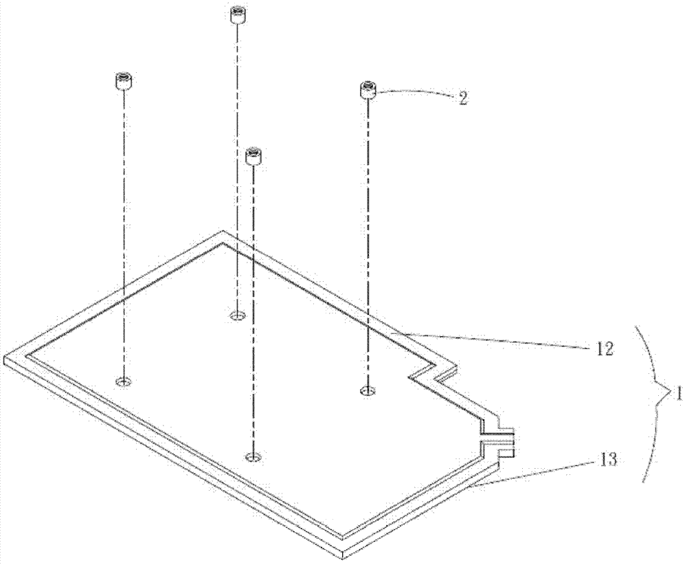
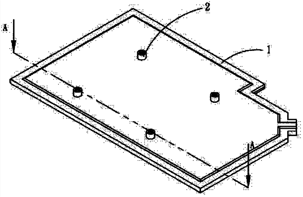
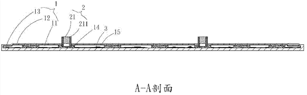
[0058] see figure 1 , figure 2 , image 3 , is the first embodiment of the fixed structure of the heat dissipation element of the present invention, the three-dimensional exploded and assembled view and the A-A sectional view, as shown in the figure, the fixed structure of the heat dissipation element of the present invention includes: a body 1, a plurality of fixed elements 2 ;

[0059] The body 1 has a chamber 11 and a first side 12 and a second side 13, the chamber 11 has a plurality of supports 14, working fluid 3 and at least one capillary structure layer 15, the supports 14 are Connecting the aforementioned first and second sides 12, 13, the capillary structure layer 15 is completely attached to the aforementioned chamber 11

[0060] The fixing element 2 has a hole 21 , and ...


PUM


Abstract

A fixing structure of a radiating element comprises a body and a plurality of fixing elements. The body is provided with a chamber, a first side and a second side, the chamber is provided with a plurality of supports, working fluid and at least one capillary structure layer, the supports are connected with the first side and the second side, and one end of each fixing element penetrates through the first side of the body and the corresponding support and is combined with the body. The fixing structure has the advantages that leakage can be prevented, air tightness of the chamber in the radiating element can be guaranteed, and the radiating element can be closely combined with other elements.

Description

technical field [0001] A fixing structure of a heat dissipation element, especially a fixing structure of a heat dissipation element, which does not destroy the heat dissipation element when it is installed, thereby preventing the internal cavity of the heat dissipation element from leaking and affecting the heat transfer efficiency of the heat dissipation element. . Background technique [0002] As the current electronic equipment is gradually advertised as light and thin, the size of each component must be reduced accordingly. However, the heat generated by the reduction in the size of electronic equipment has become a major obstacle to the improvement of the performance of electronic equipment and systems. Despite the ever-shrinking dimensions of the semiconductors forming electronic components, there is a continuing demand for increased performance. [0003] As semiconductors shrink in size, the resulting heat flux increases. The heat flux increase creates challenges in...

Claims


Application Information

Patent Timeline
IPC IPC(8): H05K7/20H01L23/40H01L23/427
Inventor 连正男
Owner ASIA VITAL COMPONENTS SHENZHEN CO LTD
Why Eureka
Try Eureka