
Backlight module and display element

A technology of a backlight module and a display element, applied in the field of backlight modules and their application structures, can solve the problem that the size of the frame cannot be effectively reduced, etc.

Active Publication Date: 2013-03-13
AU OPTRONICS CORP
View PDF6 Cites 5 Cited by
  • Summary
  • Abstract
  • Description
  • Claims
  • Application Information

AI Technical Summary

Problems solved by technology

[0005] The present invention proposes a backlight module and a display element to solve the problem that the frame size of the existing backlight module cannot be effectively reduced

Method used


Image

  • Backlight module and display element
  • Backlight module and display element
  • Backlight module and display element

Examples


Embodiment Construction

[0066] The present invention provides a backlight module with a narrow frame structure to solve the problem that the size of the frame of the existing backlight module cannot be effectively reduced. In order to make the above-mentioned and other purposes, features and advantages of the present invention more obvious and understandable, several backlight modules with narrow frame structures and display devices using such backlight modules are cited as preferred embodiments below, and In conjunction with the accompanying drawings, a detailed description is as follows.

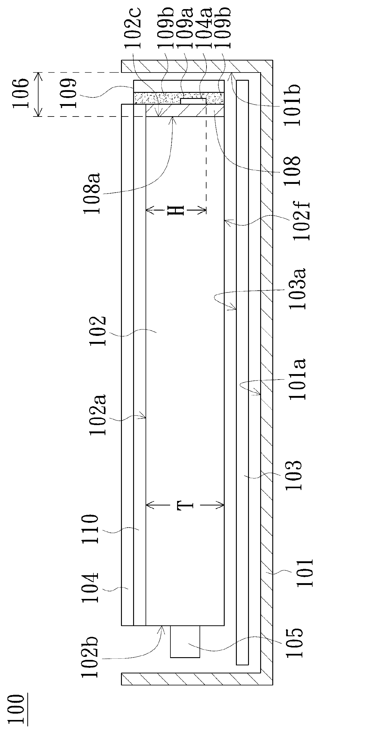
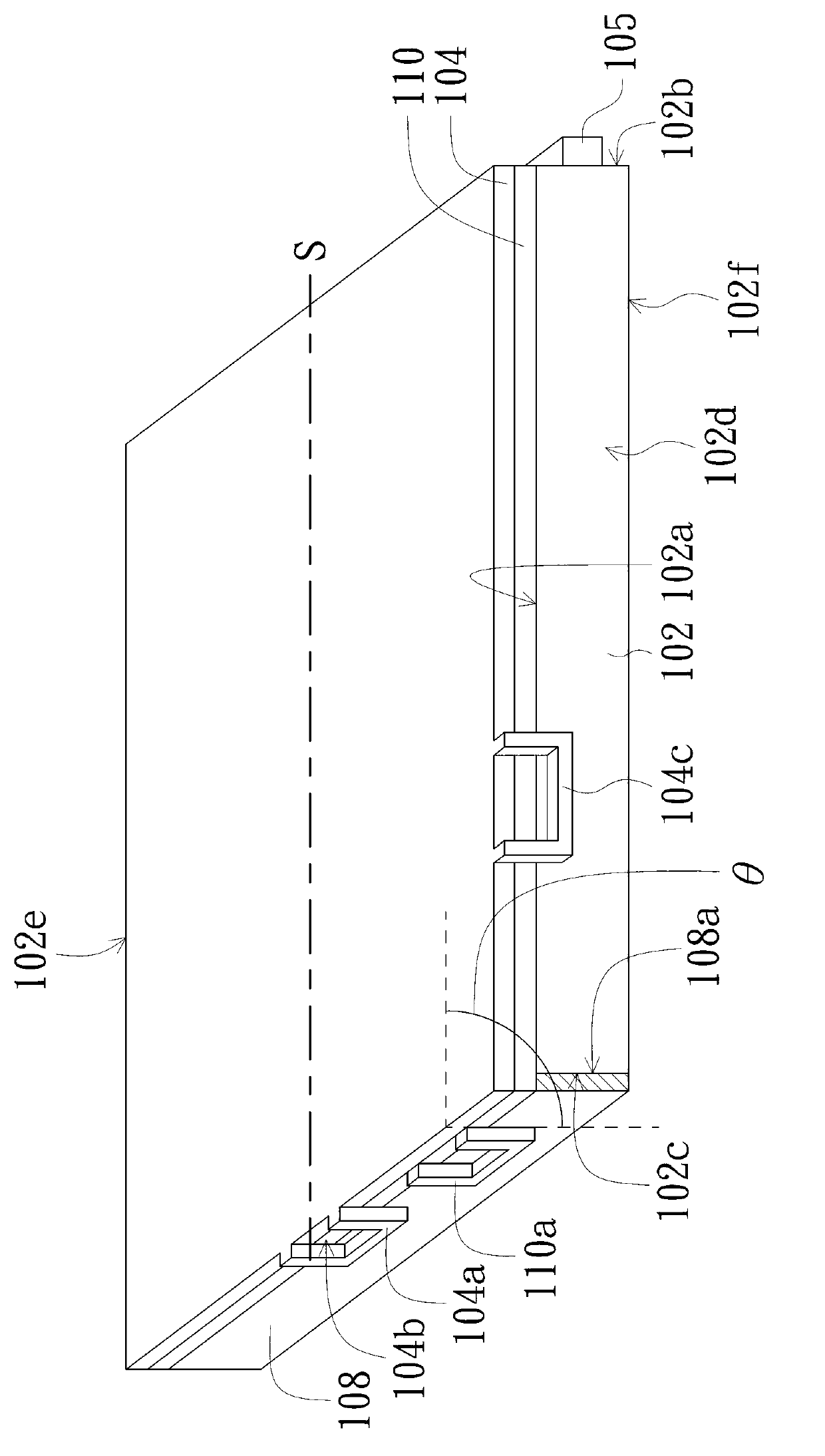
[0067] Please refer to Figure 1A and Figure 1B , Figure 1A According to an embodiment of the present invention, it is a schematic cross-sectional view of an edge-lit backlight module 100 with a narrow frame structure. Figure 1B is based on Figure 1A A schematic diagram of a partial three-dimensional structure of the backlight module 100 is shown. in, Figure 1A roughly along Figure 1B tangent S to be dra...


PUM


Abstract

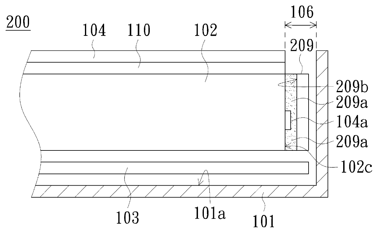
Provided are a backlight module and a display element. The backlight module comprises a housing, an optical plate, a light source, a reflective sheet and an optical film. The optical plate is positioned in the housing, and has a light outlet surface, a light inlet surface and a first side surface connected with the light outlet surface. The light source is adjacent to the light inletl surface. The reflective sheet is positioned between the housing and the optical plate, and faces opposite to the light outlet surface. The optical film faces the light outlet surface and has an extension portion extending between the housing and the first side surface. The backlight module has the technical advantages of enabling the width of a frame to be minimized and accords with requirements for a current design of the backlight module with a small frame.

Description

technical field [0001] The present invention relates to a backlight module and its application structure, and in particular to a backlight module with a narrow frame structure and its application structure. Background technique [0002] With the vigorous development of the optoelectronic industry, liquid crystal displays (LCD for short) are widely used in televisions (Television; TV), monitors (monitors), notebook computers (notebooks; NB), personal digital assistants (personal digital assistants) assistant; PDA) and mobile phone (cell phone) and other electronic devices. However, the liquid crystal display is a non-self-illuminating flat-panel display, which needs to be illuminated by an external backlight or side light. Therefore, a backlight module is used as a light source in a liquid crystal display, and the high-brightness and high-uniformity illumination of the backlight module enables the liquid crystal display to efficiently display high-quality pictures. [0003]...

Claims


Application Information

Patent Timeline
Patent Type & Authority Applications(China)
IPC IPC(8): F21S8/00F21V17/00G02F1/13357
Inventor 王耀祥范光宇吕治宇
Owner AU OPTRONICS CORP
Learn More