
The Modeling Method of Layer Velocity Model of Formation

A modeling method and layer velocity technology, applied in the field of seismic exploration, can solve problems such as difficulty in expressing velocity structure, divergence in velocity iterative process, difficulty in constraint of velocity volume interpolation and calculation, etc., and achieve a good global effect

Active Publication Date: 2015-08-05
BC P INC CHINA NAT PETROLEUM CORP +1
View PDF4 Cites 0 Cited by
  • Summary
  • Abstract
  • Description
  • Claims
  • Application Information

AI Technical Summary

Problems solved by technology

However, there is a large difference between the average velocity and the RMS velocity when the velocity varies laterally
This will cause the divergence of the velocity iteration process. Therefore, when many complex structures and velocity lateral changes exist, the accuracy and stability of the method will be affected. Its basic assumption limits its application to the situation where the stratum is a horizontal layer or the underground structure is relatively simple. This limits the application of the method to some extent
The common disadvantages of these methods are that they are not suitable for lateral drastic changes in velocity and inclined stratigraphic structures.
For the establishment of velocity model based on migration iterative velocity analysis, its biggest advantage is that it has good globality, and it is convenient and quick to deal with various types of velocity bodies. The biggest difficulty is that it is difficult to express the complex velocity structure; for variable velocity modeling The establishment of the layer velocity model of technology, its biggest advantage is that it can establish accurate formation velocity control points in the well control area, and can express more complex velocity structures. The biggest disadvantage is that it lacks globality, and it is difficult to constrain the interpolation and calculation of the velocity body

Method used


Image

  • The Modeling Method of Layer Velocity Model of Formation

Examples


Embodiment Construction

[0028] Hereinafter, exemplary embodiments according to the present invention will be described in detail with reference to the accompanying drawings.

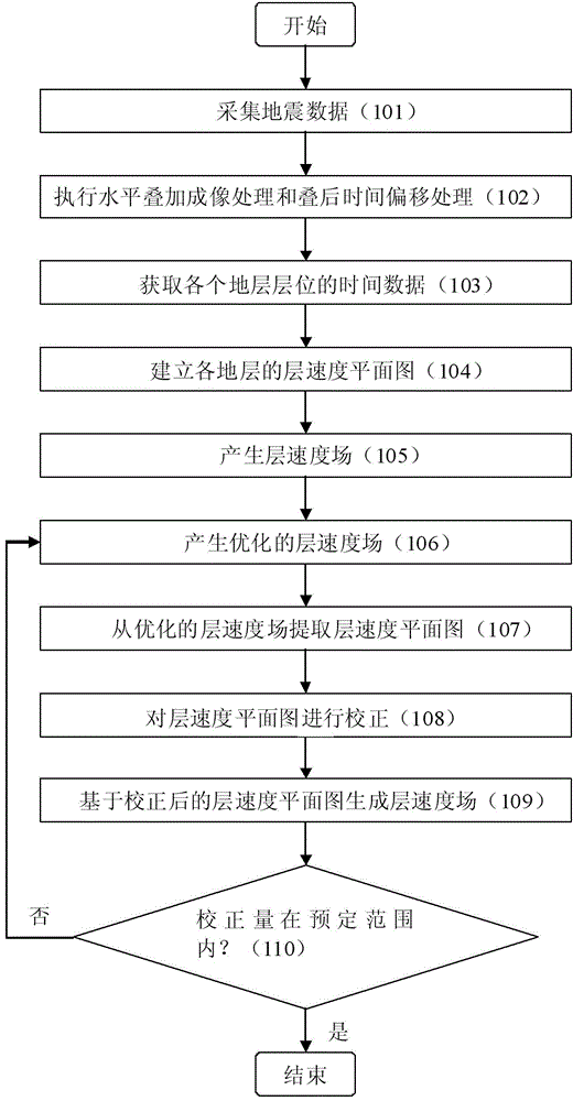
[0029] figure 1 A flowchart illustrating a modeling method of a layer velocity model of a formation according to an embodiment of the present invention.

[0030] In step 101, a seismic wave excitation method is used to generate seismic waves in the work area, and seismic data are collected.

[0031] In step 102, conventional horizontal stack imaging processing and post-stack time migration imaging processing are performed on the seismic data, thereby obtaining horizontal stack imaging data and post-stack time migration imaging data.

[0032] Horizontal stacking imaging processing and post-stack time migration imaging processing are relatively mature technologies. The more common post-stack time migration imaging processing is to perform post-stack time migration on the horizontal stacked imaging data after proper correction o...


PUM


Abstract

The invention provides a method for building a layer velocity model of a stratum. The method comprises the following steps of: acquiring earthquake-related data of a work area; generating a layer velocity field by utilizing the earthquake-related data and drilling data of the work area; carrying out velocity iteration processing on the layer velocity field by using a reflection tomography method to generate an optimized layer velocity field; extracting a layer velocity planar graph of each stratum from the optimized layer velocity field; correcting the extracted layer velocity planar graph of each stratum by utilizing the drilling data; generating a layer velocity field based on the corrected layer velocity planar graph; and carrying out the velocity iteration processing step on the generated layer velocity field by using the reflection tomography method when the correcting value exceeds a preset range.

Description

technical field [0001] The present invention relates to the field of seismic exploration. More specifically, it relates to a modeling method for obtaining a layer velocity model of a formation using seismic data. Background technique [0002] Under the condition of steep and complex structure, the correct imaging of subsurface medium can only be obtained by prestack depth migration from artificial seismic data. However, prestack depth migration can only be imaged correctly if the layer velocity model is accurate. Where prestack depth migration is required, conventional velocity analysis methods often fail to meet the desired accuracy requirements. In this case, in order to obtain a more accurate layer velocity model, a velocity analysis method based on migration iteration was developed. Now it can be said that migration velocity analysis is velocity analysis using migration iteration. This type of velocity analysis method uses the influence of velocity field on migration ...

Claims


Application Information

Patent Timeline
Patent Type & Authority Patents(China)
IPC IPC(8): G01V1/28G01V1/30
Inventor 章雄朱亚东庞崇友刁永波李龙江
Owner BC P INC CHINA NAT PETROLEUM CORP
Learn More