
Sensing circuit and sensing method of capacitive touch panel

A technology of capacitive touch and sensing circuit, applied in the field of sensing, to achieve the effect of simple and simple hardware circuit structure, low circuit complexity, and low power consumption

Active Publication Date: 2013-03-13
ORISE TECH CO LTD
View PDF3 Cites 28 Cited by
  • Summary
  • Abstract
  • Description
  • Claims
  • Application Information

AI Technical Summary

Problems solved by technology

[0003] At present, the implementation structure of the sensing circuit of the self-capacitance positioning (sensing) method is not unified, but in order not to affect the power durability of the (handheld) electronic products used in the projected capacitive touch panel when it is in standby, so How to design a self-inductance (capacitance) sensing circuit with low circuit complexity and low power consumption for application in a projected capacitive touch panel is one of the subjects that the technicians / developers in the field related to the present invention are working hard on.

Method used


Image

  • Sensing circuit and sensing method of capacitive touch panel
  • Sensing circuit and sensing method of capacitive touch panel
  • Sensing circuit and sensing method of capacitive touch panel

Examples


Embodiment Construction

[0031] In order to make the purpose, technical solution and advantages of the present invention more clear, the present invention will be further described in detail below with reference to the accompanying drawings and examples.

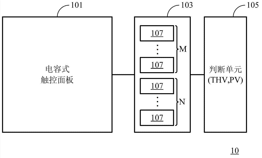
[0032] figure 1 Shown is a schematic diagram of a capacitive touch apparatus (capacitive touch apparatus) 10 according to an exemplary embodiment of the present invention. see figure 1 , the capacitive touch device 10 includes: a capacitive touch panel (capacitive touch panel) 101 , a sensing device (sensing device) 103 , and a judgment unit (judgment unit) 105 . Wherein, the capacitive touch panel 101 may be a projected capacitive touch panel (projective capacitive touch panel), but not limited thereto. Under this condition, the (projected) capacitive touch panel 101 may include M×N sensing capacitors (not shown in the figure) defined by the XY electrodes, and M×N is represented as a (projected) capacitance The sensing resolution (sensing resolu...


PUM


Abstract

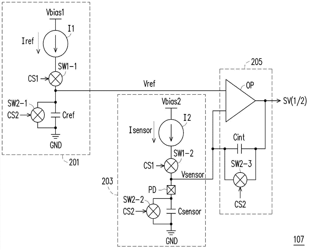
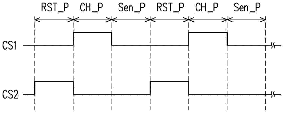
The invention discloses a sensing circuit and a sensing method of a (projective) capacitive touch panel. The sensing circuit comprises a reference voltage generating unit, a sensing voltage generating unit and an integral judgment unit, wherein the reference voltage generating unit comprises a preinstalled reference capacitor, and is configured to charge the preinstalled reference capacitor so as to generate a reference voltage; the sensing voltage generating unit is configured to charge at least one sensing capacitor in the (projective) capacitive touch panel so as to generate a sensing voltage; and the integral judgment unit is used to receive and judge whether boosting speeds of the reference voltage and the sensing voltage are identical so as to output a sensing voltage value.

Description

technical field [0001] The present invention relates to the field of sensing technology, in particular to a sensing circuit of a projected capacitive touch panel and a sensing method thereof. Background technique [0002] The working principle of the projected capacitive touch panel is mainly to detect the capacitance change caused by the electrostatic capacitance of the finger to the inductive capacitance formed between the XY electrodes in the projected capacitive touch panel. Common positioning (sensing) methods for projected capacitive touch panels include self-capacitance (or self-inductance) and mutual-capacitance (mutual-inductance). Taking the self-capacitance positioning (sensing) method as an example, multiple sensing circuits in two directions (XY axes) will be connected to each XY electrode, and which X electrodes and Y electrodes are detected by these sensing circuits. Capacitance changes can be used to know the user's single or multiple touch points on the pro...

Claims


Application Information

Patent Timeline
Patent Type & Authority Applications(China)
IPC IPC(8): G06F3/044
Inventor 黄世新黄彦霖
Owner ORISE TECH CO LTD
Learn More