Mold press plate

A mold pressing plate and pressing plate technology, which is applied in the direction of manufacturing tools, clamping, supporting, etc., can solve the problems of small adjustment range, decreased clamping fastness, and inability to adjust back and forth, so as to increase the adjustment range and increase the clamping strength. High, to meet the effect of high needs

Inactive Publication Date: 2015-03-18
朱华丰
View PDF8 Cites 1 Cited by
  • Summary
  • Abstract
  • Description
  • Claims
  • Application Information

AI Technical Summary

Problems solved by technology

Its shortcoming is that the pressing surfaces at both ends of the pressing plate are fixed, which brings certain troubles to the clamping of some angled and tapered products, and the fastness of the clamping will also decrease accordingly.
However, this kind of folding gasket can only be adjusted up and down, and cannot be adjusted back and forth, so that the adjustment range is small, which cannot well meet the needs of mold clamping, and the adjustment is more troublesome.

Method used


Image

  • Mold press plate
  • Mold press plate
  • Mold press plate

Examples


Embodiment Construction

[0023] The present invention will be further described in detail below in conjunction with the accompanying drawings and embodiments.

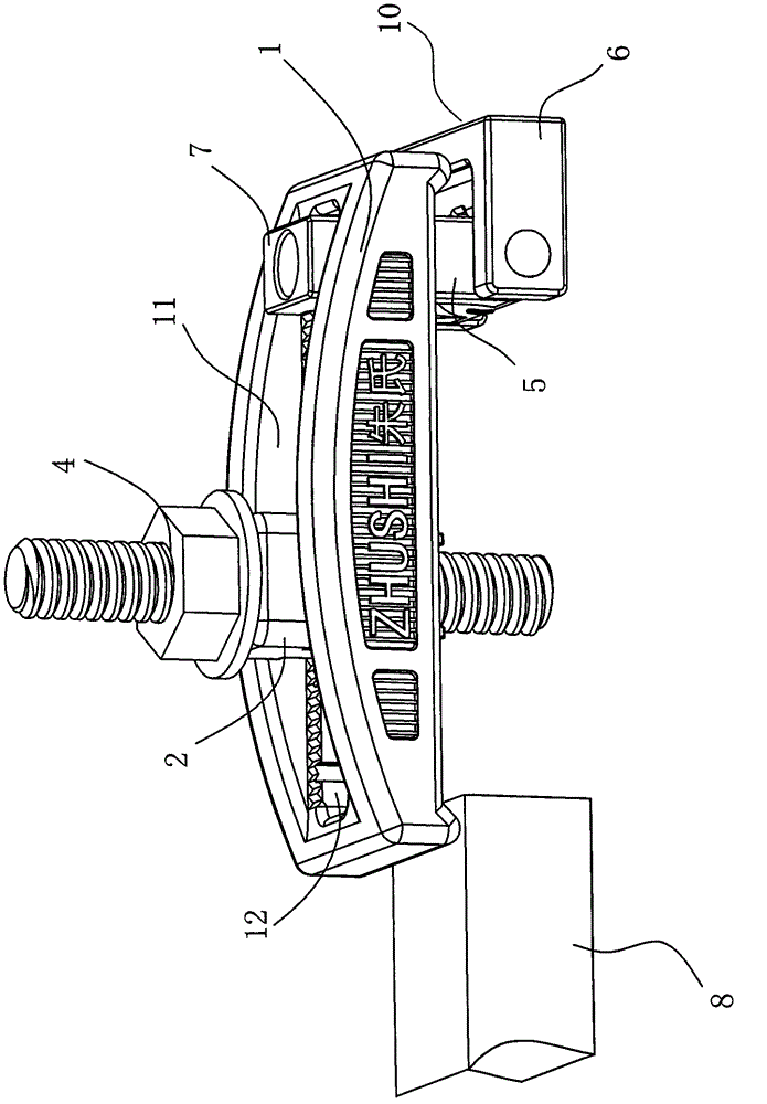
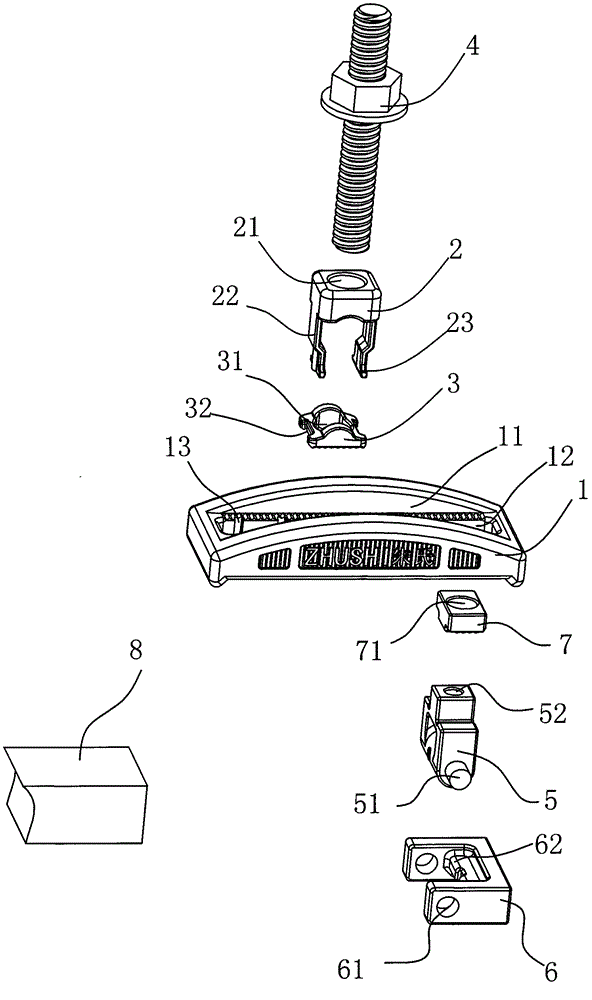
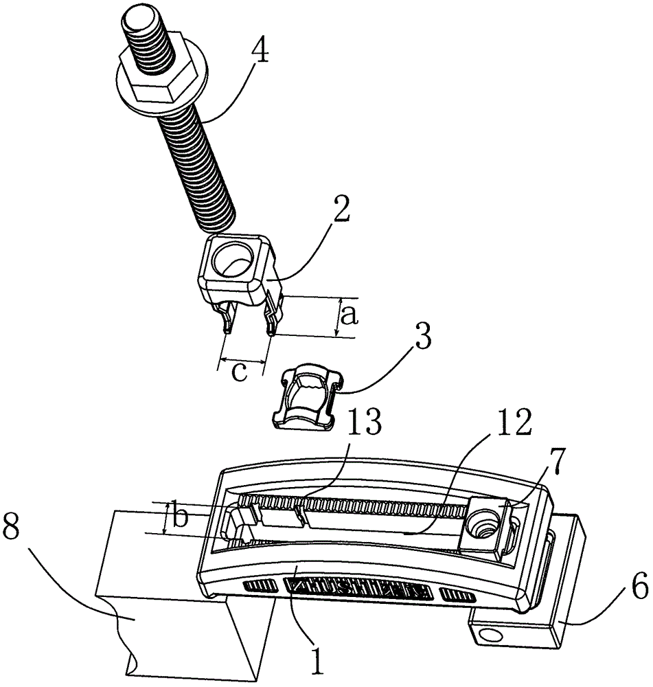
[0024] As shown in the figure, a mold pressing plate includes a pressing plate main body 1, a lower cushion block 3 and an upper cushion block 2 arranged on the lower cushion block 3, wherein a longitudinal groove 11 is provided in the middle of the upper surface of the pressing plate main body 1, A longitudinal through hole 12 is opened at the bottom of the longitudinal groove 11, and the upper spacer 2 and the lower spacer 3 are fitted with an arc surface, and the two are seated in the longitudinal groove 11 and rested on the On the bottom surface of the above-mentioned longitudinal groove 11, an upper through hole 21 and a lower through hole corresponding to the position of the above-mentioned longitudinal through hole 12 and allowing the screw rod 4 to pass through are provided in the middle of the upper pad 2 and the lower pad 3 31. These...


PUM


Abstract

A mold press plate comprises a press plate main body, a lower cushion block and an upper cushion block arranged on the lower cushion block, wherein the middle of the upper surface of the press plate main body is provided with a longitudinal groove, a longitudinal through hole is formed at the bottom of the groove, the upper cushion block and the lower cushion block are matched in a cambered surface mode, the upper cushion block and the lower cushion block are both located in the longitudinal groove and are placed on the bottom face of the longitudinal groove, meanwhile the middle of the upper cushion block and the middle of the lower cushion block are provided with an upper through hole and a lower through hole which correspond to the position of the through hole and allow a screw to penetrate. The mold press plate is characterized in that a base plate is arranged on the lower portion of one end of the press plate main body, and the upper end of the base plate is limited in the longitudinal through hole and can move forwards and backwards along the longitudinal through hole. The base plate can be regulated forwards and backwards, and can also be regulated upwards and downwards, so the regulation range is widened, height requirements for different workpiece molds can be met, clamping strength is high, and the utilization and regulation are both convenient; and the overall structure is simple, reasonable and practical.

Description

technical field [0001] The invention relates to a machine tool accessory fixture, in particular to a mold pressing plate for fixing a workpiece or mold to be processed on the table of the machine tool. Background technique [0002] The mold clamp is the simplest and most commonly used fixture in the machining industry. The traditional flat mold clamp is used together with the pad. Depending on the thickness of the workpiece, the pad must be replaced accordingly, but it is often prone to drop and loss due to the pad. Because of this reason, it is gradually replaced by mold pressing plates of various structures in the existing market. [0003] Such as the Chinese utility model patent No. 99206225.X, which includes a pressing plate with a long groove in the longitudinal direction and a pair of upper and lower pads on the string for pressing screws. It is characterized in that the pressing plate is arched, and on its back There is a row of finely distributed racks along both si...

Claims


Application Information

Patent Timeline
Patent Type & Authority Patents(China)
IPC IPC(8): B23Q3/08
Inventor 朱华丰
Owner 朱华丰
Why Eureka
Try Eureka