Automatic pressure release tank cover structure for firefighting truck water tank

A fire truck and automatic venting technology, applied in underwater structures, infrastructure engineering, construction, etc., can solve the problems of fragile effect, insufficient to reflect the quick opening and closing effect of the tank cover, insufficient to reflect the labor-saving effect of operation, etc. To achieve the effect of convenient manufacture and installation, simple overall structure, and reliable grip

Inactive Publication Date: 2013-03-20
JIEDA FIRE PROTECTION VEHICLE EQUIP CO LTD SUZHOU CITY
View PDF8 Cites 0 Cited by
  • Summary
  • Abstract
  • Description
  • Claims
  • Application Information

AI Technical Summary

Problems solved by technology

[0003] The above-mentioned CN100586059C effectively makes up for the four shortcomings of the tank cover structure previously arranged on the top of the liquid storage tank. For details, please refer to page 1, page 15- 22 lines, and this patent scheme objectively embodies the technical effect of lines 5-9 on page 3 of its specification, but there are still the following shortcomings: First, the operation of opening or closing and locking the can lid is cumbersome and time-consuming, because the patent The solution is to lock or release the can lid through a set of (usually three or four) complex-structured latches arranged at intervals on the outer wall of the can lid seat, so when the can lid is to be opened or closed, it must be Because a tool such as a wrench can fully operate a set of locking parts; second, when the firefighter moves the tank cover from the tank cover seat for the inspection personnel to enter the liquid storage tank, because the shape of the tank cover tends to the shape of the pot cover, Therefore, it is not easy to grasp and pinch, thereby increasing physical exertion, and the same is true for the operation of returning the can lid to the can lid seat; the third is that the structure is relatively complicated, and both manufacturing and installation are relatively troublesome
[0004] Publication No. CN101214408A provides an "automatic pressure relief tank for fire truck water tank", the patent application scheme overcomes the defects of CN1961995A, and can also objectively reflect the The technical effects summarized in lines 1 to 6 on page 3 of the specification, especially, compared to the aforementioned CN100586509C, the time for opening or locking the can lid can be significantly shortened and the structure can be significantly simplified, but it is still exposed during actual use. The following disadvantages are found: one, because opening or closing the tank cover still needs to be operated by eliminating personnel with the help of a tool such as a wrench on the fixing nut of the locking device (the patent is called a locking device), it is still not enough to reflect the speed of the tank cover. That is, the effect of opening and closing, so that the operating time of firefighters cannot be saved to the greatest extent; second, whether it is lifting the tank cover or returning to the tank cover seat, it is not enough to reflect the labor-saving effect of the operation; third, because the tank cover control rack The effect of forcing the can lid to fit closely with the can lid seat is weak, so there is a risk of poor closure of the can lid

Method used


Image

  • Automatic pressure release tank cover structure for firefighting truck water tank

Examples


Embodiment Construction

[0019] In order to enable the examiners of the patent office, especially the public, to understand the technical essence and beneficial effects of the present invention more clearly, the applicant will describe in detail the following in the form of examples, but none of the descriptions to the examples is an explanation of the solutions of the present invention. Any equivalent transformation made according to the concept of the present invention which is merely formal but not substantive shall be regarded as the scope of the technical solution of the present invention.

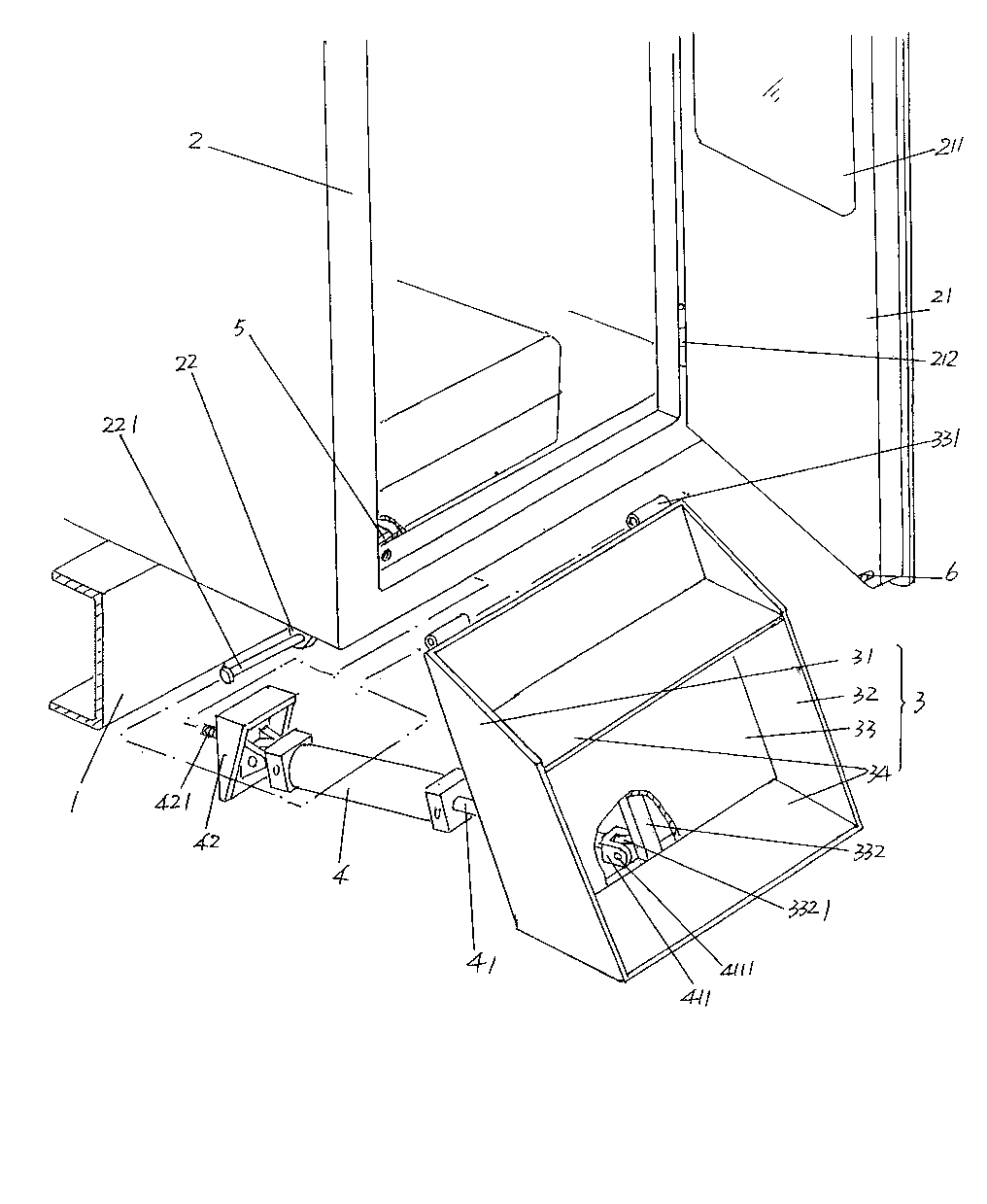
[0020] See figure 1 , provides a fire engine water tank, the fire engine water tank includes a liquid storage tank 1, a circular manhole 11 is opened on the top of the liquid storage tank 1, and a protrusion is formed around the circumferential direction of the manhole 11 The tank cover seat 111 on the top surface of the liquid storage tank 1 .

[0021] The first connecting seat 2 and the second conne...


PUM


Abstract

The invention discloses an automatic pressure release tank cover structure for a firefighting truck water tank, which belongs to a firefighting facility. The automatic pressure release tank cover structure comprises a liquid storing tank, a first connecting seat and a second connecting seat, wherein the top of the liquid storing tank is provided with a manhole; a tank cover base is formed in the circumferential direction of the manhole; the first connecting seat and the second connecting seat are kept 180 degrees away from each other along the circumferential direction of the tank cover base; the tank cover and the tank cover base are matched with each other in a covering way; a floating connecting mechanism is arranged in the center of the tank cover, and is connected with the middle part of a tank cover pipe frame; and the tank cover pipe frame is matched with the first connecting seat and the second connecting seat. The automatic pressure release tank cover structure is characterized by further comprising a bare hand operating arm and a safety pin, wherein one end of the bare hand operating arm is matched with the first connecting seat, and is connected with one end of the tank cover pipe frame; the middle part of the bare hand operating arm is provided with a lock pin flange probing hole; the other end of the bare hand operating arm is made into a handle; one end of the tank cover pipe frame is made into a lock pin flange; and the safety pin is matched with the lock pin flange. The automatic pressure release tank cover structure has the advantages that the tank cover can be opened or closed rapidly in a bare-handed state; operation is performed in a labor-saving way, and gripping is reliable; the closing effect is good; and convenience is brought to manufacturing and installation.

Description

technical field [0001] The invention belongs to the technical field of fire-fighting facilities, and in particular relates to an automatic pressure-relieving tank cover structure for a water tank of a fire truck. Background technique [0002] As known to professionals in the field of firefighting technology, in addition to being provided with a liquid filling port for filling the liquid storage tank with fire extinguishing fluid such as water on the top of the liquid storage tank of the fire truck (people are used to calling it a water tank or a fire extinguishing foam tank), there is also a There are manholes. The function of the manhole is for firefighters to enter the liquid storage tank to inspect or clean the liquid storage tank. Since the manhole needs to be closed when the fire truck is in use, the manhole is equipped with a tank cover, and The tank cover also has a pressure relief function, for which reference can be made to the "tank cover structure for fire trucks"...

Claims


Application Information

Patent Timeline
Patent Type & Authority Applications(China)
IPC IPC(8): B65D90/10
Inventor 崔小锋
Owner JIEDA FIRE PROTECTION VEHICLE EQUIP CO LTD SUZHOU CITY
Why Eureka
Try Eureka