Fuel-atomizing integrated igniter

A fuel atomization and igniter technology, which is used in combustion ignition, combustion methods, lighting and heating equipment, etc., can solve the problems of forming a stable ignition source in the area that is not easy to return, unable to ensure stable combustion, and flame blowing out, etc. Achieve reliability, easy replacement of parts, and reliable ignition

Inactive Publication Date: 2013-03-20
HARBIN ENG UNIV
View PDF9 Cites 12 Cited by
  • Summary
  • Abstract
  • Description
  • Claims
  • Application Information

AI Technical Summary

Problems solved by technology

[0003] In the actual ignition process, due to the arrangement of the igniter and the intersection, the high-speed fuel sprayed by the nozzle will blow down the high-energy plasma arc generated by the igniter, which will easily blow out the flame; the fuel will be ignited downstream of the igniter, and it is not easy to flow back The region forms a stable ignition source, which cannot ensure stable combustion

Method used


Image

  • Fuel-atomizing integrated igniter

Examples


Embodiment Construction

[0018] The present invention will be described in more detail below with examples in conjunction with the accompanying drawings.

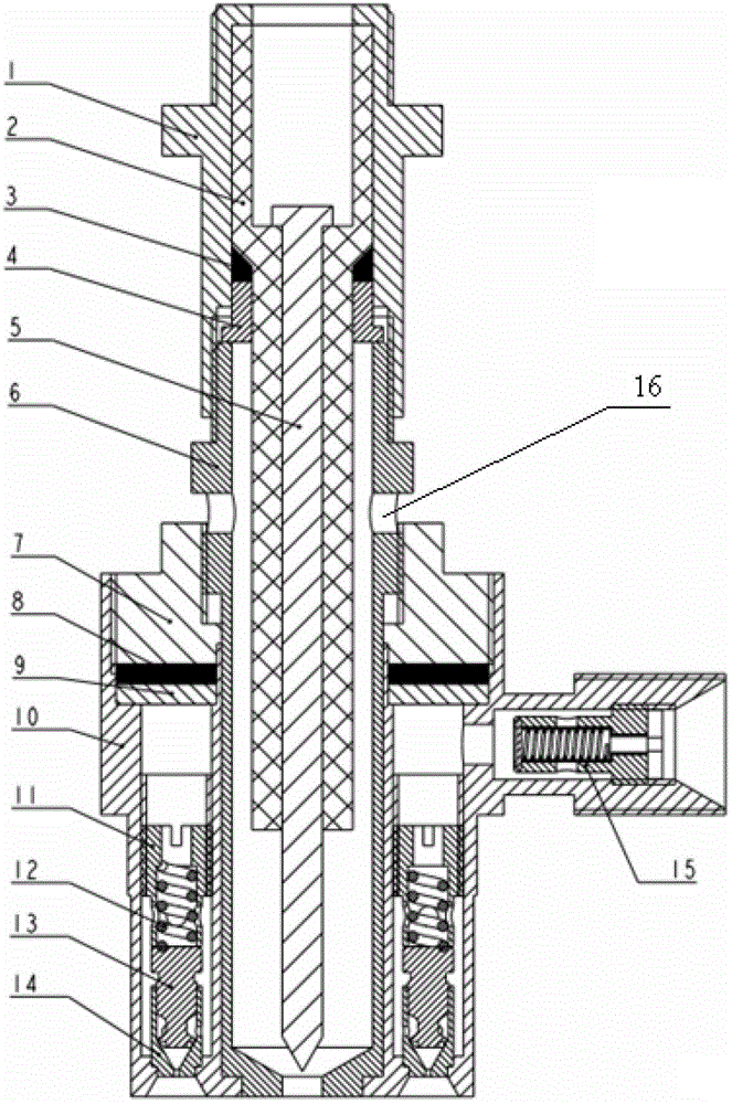
[0019] The structural composition of the fuel atomization integrated igniter of the present invention mainly includes: power connector 1, ceramic insulating medium 2, graphite sealing ring 3, support ring 4, inner electrode 5, grounding electrode 6, compression cover 7, sealing gasket 8 , Compression ring 9, fuel atomization assembly housing 10, fixed hollow nut 11, support spring 12, swirler 13, swirler housing 14, oil filter 15, air guide hole 16.

[0020] An air plasma igniter composed of an inner electrode 5 located in the center, a ground electrode 6 located outside the inner electrode, a ceramic insulating medium 2 between the inner electrode and the ground electrode, and a power connector 1. A supporting ring 4 is arranged between the ground electrode and the ceramic insulating medium, a certain gap is formed between the ground electrode and...


PUM


Abstract

The invention provides a fuel-atomizing integrated igniter which comprises an air plasma igniter and a fuel-atomizing jetting component, wherein the air plasma igniter is mainly composed of an inner electrode, a grounding electrode, an insulating medium and a power supply connector; the fuel-atomizing jetting component is mainly composed of a fuel-atomizing component shell and fuel-atomizing components; each of the fuel-atomizing components comprises a swirler shell and a swirler mounted in the swirler shell; the fuel-atomizing component shell is of annular shape; the plurality of fuel-atomizing components are uniformly distributed in the annular fuel-atomizing component shell; the annular fuel-atomizing component shell is provided with a fuel inlet; a fuel filter is arranged on the fuel inlet; the air plasma igniter is located in the annular fuel-atomizing component shell; an air guiding hole is formed on the grounding electrode; and the fuel-atomizing component shell and the grounding electrode are integrally connected through a pressing cover. The fuel-atomizing integrated igniter is applied to the field of thermal energy and power engineering; the generation of the conditions, such as, retrocession of an ignition source, flame blow-out, and the like, caused by horizontal jetting is avoided; and the reliability of ignition is increased.

Description

technical field [0001] The invention relates to a device combining an air plasma igniter and a fuel atomizing nozzle. Background technique [0002] In the combustion chamber of a gas turbine, the igniter and the fuel nozzle are arranged separately. The fuel nozzle is located at the center of the combustion chamber head, and the igniter is located at the upper rear of the combustion chamber head. The ignition position should be just on the flame surface to ensure ignition success. The flame further propagates to the central recirculation zone, thus forming a stable ignition source to ensure stable combustion. [0003] In the actual ignition process, due to the arrangement of the igniter and the intersection, the high-speed fuel sprayed by the nozzle will blow down the high-energy plasma arc generated by the igniter, which will easily blow out the flame; the fuel will be ignited downstream of the igniter, and it is not easy to flow back The zone forms a stable ignition sourc...

Claims


Application Information

Patent Timeline
Patent Type & Authority Applications(China)
IPC IPC(8): F23Q13/00
Inventor 李雅军郑洪涛刘倩
Owner HARBIN ENG UNIV
Why Eureka
Try Eureka