Boost circuit without switching device for electrical equipment

A booster circuit, no-switch technology, applied in the conversion equipment that can be converted to DC without intermediate conversion, and the conversion of irreversible AC power input to DC power output, etc. question

Inactive Publication Date: 2013-03-20
JIANGSU JIAYU NEW POWER TECH
View PDF10 Cites 1 Cited by
  • Summary
  • Abstract
  • Description
  • Claims
  • Application Information

AI Technical Summary

Problems solved by technology

However, there is a problem that the switching device is short-circuited to the negative pole instantaneously during operation. Once the short-circuit time exceeds the design value, it will cause a short-circuit and burn the device.
[0004] The third type is voltage doubler rectification, which uses diodes and capacitors to form a voltage doubler rectifier circuit to achieve boosting. High voltage capacitors and high voltage diodes are used, which are large in size and high in cost, and are generally only used in low-power and micro-power circuits.
[0005] The first and second types of circuits must use switching devices, which brings additional loss and cost increase, and because of the existence of switching devices, the life span is greatly reduced
Moreover, in normal operation, the switching device needs to have a huge instantaneous current stress, and the boosted voltage value is all superimposed on the switching device, and the voltage stress is also very large, which increases the cost of the device and makes it difficult to greatly increase the output voltage.

Method used


Image

  • Boost circuit without switching device for electrical equipment

Examples


Embodiment Construction

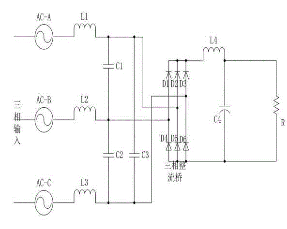
[0013] Such as figure 1 , the present invention includes a three-phase diode rectification full bridge connected by six rectifier diodes D1~D6 in the form of a bridge full-wave rectification circuit, and a DC filter inductor is connected between the positive pole of the output terminal of the three-phase diode rectification full bridge and the positive pole of the load R L4, the negative pole of the load R is connected to the negative pole of the output terminal of the three-phase diode rectifier full bridge, and the DC filter capacitor C4 is connected in parallel at both ends of the load R. The specific parameters of the DC filter inductor L4 have a great impact on the harmonic current, and have a negligible impact on the boost effect. The DC filter capacitor C4 can be calculated by conventional filtering methods.

[0014] Three identical boost inductors L1, L2, and L3 are connected in series between the three-phase input and the input end of the three-phase diode rectified f...


PUM


Abstract

The invention discloses a boost circuit without a switching device for electrical equipment. The boost circuit comprises a three-phase diode rectifying full bridge formed by connecting six rectifying diodes (D1 to D6) according to a bridge type full wave rectifying circuit manner, and is characterized in that three same boost inductors (L1, L2 and L3) are respectively connected in series between three phases of input terminals and input terminals of the three-phase diode rectifying full bridge, and three same boost capacitors (C1, C2 and C3) are respectively connected in parallel among the input terminals of the three-phase diode rectifying full bridge. The switching device is not used, and through arranging the LC devices with suitable parameters on a three-phase rectifying loop, the aim of low-voltage input and high-voltage output can be realized, thereby prolonging the service life of the boost circuit and improving the reliability thereof.

Description

technical field [0001] The invention relates to a voltage boosting circuit for electric equipment. Background technique [0002] There are many electrical devices that need to operate under higher DC power, but at this time the AC power cannot be realized by simple rectification and filtering. A conventional boost circuit must have a switching circuit or a switching device, otherwise the boost cannot be achieved. The conventional boost circuit is a switching DC boost circuit, which boosts the lower voltage provided by the power supply to the required voltage value, and the output voltage is higher than the input voltage. The conventional boost circuit has three structural forms: the first one is a low-voltage high-frequency current produced by high-frequency oscillation, which is rectified to obtain high-voltage direct current after the boost transformer reaches a predetermined voltage value, and the front and rear stages of the circuit are isolated, which can reach extrem...

Claims


Application Information

Patent Timeline
IPC IPC(8): H02M7/06H02M5/06
Inventor 秦军
Owner JIANGSU JIAYU NEW POWER TECH
Why Eureka
Try Eureka