
Driving circuit and driving method thereof, panel and driving method thereof

A technology for driving electrodes and panels, applied in the field of driving, can solve the problems of insufficient driving voltage of active driving chips, unsupported passive driving chips, limited driving capability of passive driving chips, etc., and achieve the effect of being beneficial to boosting driving circuits

Active Publication Date: 2021-03-19
SHANGHAI AVIC OPTOELECTRONICS
View PDF7 Cites 1 Cited by
  • Summary
  • Abstract
  • Description
  • Claims
  • Application Information

AI Technical Summary

Problems solved by technology

The control circuit usually uses a passive drive chip, but due to the limited drive capability of the passive drive chip, when it is desired to perform a large number of chemical micro-reactions or substance detection at the same time, it is necessary to set a lot of drive electrodes
In order to provide signals for many driving electrodes, the driver chip needs to have many signal channels (pins / pins), but the current passive driver chip cannot support
[0005] In the prior art, the signal channels of the drive chip can be reduced by setting the drive electrodes and control circuits arranged in an array. At this time, the drive chip is an active drive chip, but the drive voltage and the output of the active drive chip in the prior art The voltage that can drive the droplet movement varies greatly. Generally, the voltage that can drive the droplet movement needs to be around 50V. However, according to the driving voltage of the active drive chip in the prior art, the high-voltage drive chip can generally only provide a drive of about 30V. Voltage, so the existing active driver chip has the problem of insufficient driving voltage

Method used


Image

  • Driving circuit and driving method thereof, panel and driving method thereof
  • Driving circuit and driving method thereof, panel and driving method thereof
  • Driving circuit and driving method thereof, panel and driving method thereof

Examples


Embodiment Construction

[0042] Various exemplary embodiments of the present invention will now be described in detail with reference to the accompanying drawings. It should be noted that the relative arrangements of components and steps, numerical expressions and numerical values ​​set forth in these embodiments do not limit the scope of the present invention unless specifically stated otherwise.

[0043] The following description of at least one exemplary embodiment is merely illustrative in nature and in no way taken as limiting the invention, its application or uses.

[0044] Techniques, methods and devices known to those of ordinary skill in the relevant art may not be discussed in detail, but where appropriate, such techniques, methods and devices should be considered part of the description.

[0045] In all examples shown and discussed herein, any specific values ​​should be construed as exemplary only, and not as limitations. Therefore, other instances of the exemplary embodiment may have dif...


PUM


Abstract

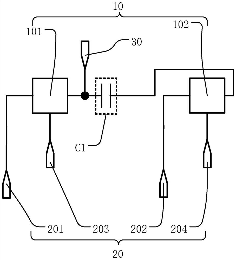
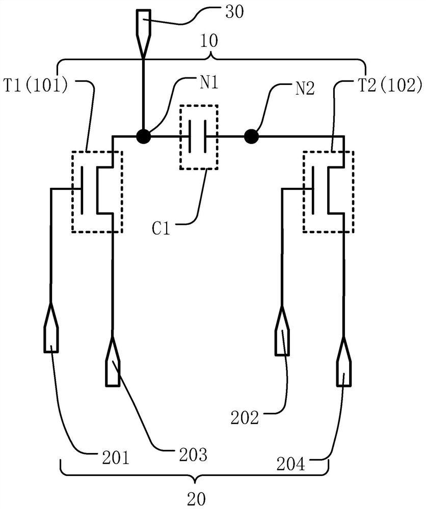
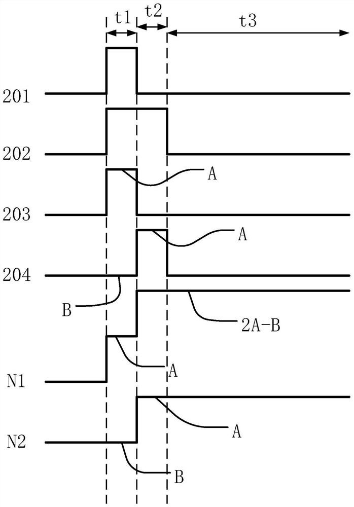
The invention discloses a driving circuit and a driving method thereof, a panel and a driving method thereof, and relates to the technical field of driving, the driving circuit comprises a boost unit,a plurality of signal input ends and a signal output end; the boost unit comprises a first module, a second module and a first capacitor; the first module is used for transmitting a signal of the third signal input end to the first end of the first capacitor; and the second module is used for transmitting a signal of the fourth signal input end to the second end of the first capacitor at first time to form a voltage difference between the two ends of the first capacitor, and transmitting a signal of the fourth signal input end to the second end of the first capacitor at second time to furtherincrease the signal of the first end of the first capacitor. The invention further provides a driving method for driving the driving circuit, a panel comprising the driving circuit and a driving method of the panel. According to the invention, low-voltage input and high-voltage output can be realized, and the panel can provide relatively high driving voltage for chemical micro-reaction or substance detection of a large batch of samples.

Description

[0001] This application is a divisional application with an application date of April 4, 2019, an application number of 201910272250.3, and an invention titled "drive circuit and its driving method, panel and its driving method". technical field [0002] The present invention relates to the technical field of driving, and more specifically, to a driving circuit and a driving method thereof, a panel and a driving method thereof. Background technique [0003] Micro Fluidics technology is an emerging interdisciplinary subject involving chemistry, fluid physics, microelectronics, new materials, biology and biomedical engineering. It can precisely control the movement of droplets and realize the fusion and separation of droplets. , to complete various biochemical reactions, is a technology whose main feature is the manipulation of fluids in the micron-scale space. This technology has intersected with various disciplines such as chemistry, biology, engineering and physics, showing...

Claims


Application Information

Patent Timeline
Patent Type & Authority Applications(China)
IPC IPC(8): G09G3/34
CPCG09G3/348G09G2300/0426G09G2300/0876G09G2310/0243B01L3/502792B01L2400/0427B01L2300/165B01L2300/0645H01L27/1255B01L3/502715B01L3/50273G01N27/228H01L27/1225H01L27/124H03K17/687
Inventor 席克瑞李小和秦锋刘金娥崔婷婷林柏全
Owner SHANGHAI AVIC OPTOELECTRONICS
Learn More