Robot system and imaging method
A robot system and robot technology, applied in general control systems, control/regulation systems, instruments, etc., can solve problems such as inability to perform proper operations
- Summary
- Abstract
- Description
- Claims
- Application Information
AI Technical Summary
Problems solved by technology
Method used
Image

Examples
no. 1 Embodiment approach )
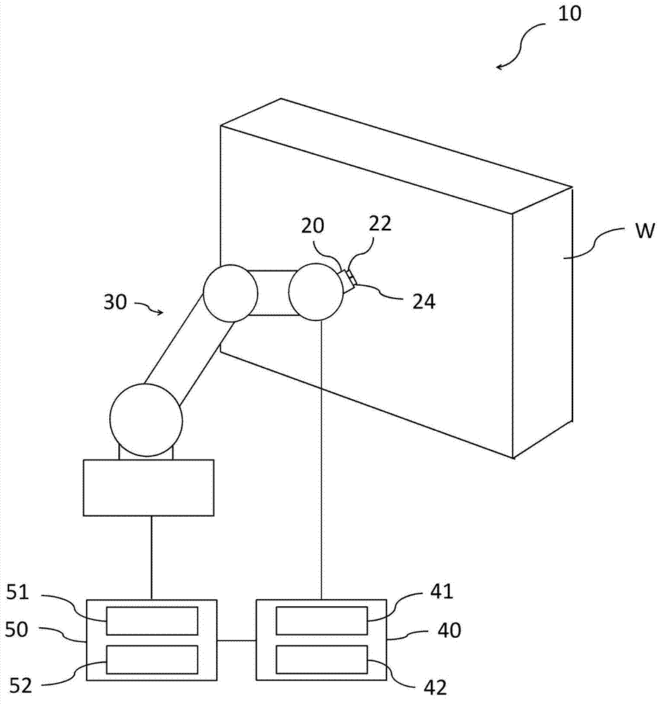
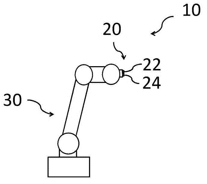
[0029] figure 1 A schematic diagram of the robot system 10 of this embodiment is shown. The robot system 10 has an imaging unit 20 , a robot 30 mounted with the imaging unit 20 , an imaging controller 40 , and a robot controller 50 . The camera unit 20 is mounted on the front end of the robot 30 . In the present embodiment, the robot 30 is an articulated robot including a plurality of actuators each having a servo motor. By driving the respective actuators, the position and direction of each part of the robot 30 can be changed, whereby the position of the entire robot 30 and the position of the imaging unit 20 can be changed.
[0030] The imaging unit 20 has an imaging device 22 and a distance measuring unit 24 . For example, the imaging device 22 and the distance measuring unit 24 are integrally provided. The imaging device 22 has, for example, a camera. The imaging device 22 captures a two-dimensional planar image. As an example, the number of pixels of the imaging dev...
no. 2 Embodiment approach )
[0060] Figure 5 A schematic diagram of the robot system 10 of this embodiment is shown. The robot system 10 of the present embodiment has the same configuration as the robot system described in the first embodiment, and redundant descriptions are omitted to avoid redundancy.
[0061] A reference image of the workpiece W is stored in the storage device 41 . The processor 42 extracts an area corresponding to the reference image stored in the storage device 41 from the image pre-captured by the imaging device 22, and obtains a degree of coincidence with the reference image. The processor 42 may also determine at least one of the direction and the distance to pre-move the imaging unit 20 based on such pattern matching.
[0062] In addition, the processor 42 may compare the image captured by the imaging device 22 with the reference image stored in the storage device 41 before and after the distance measurement. For example, the comparison is based on at least one of shape and l...
no. 3 Embodiment approach )
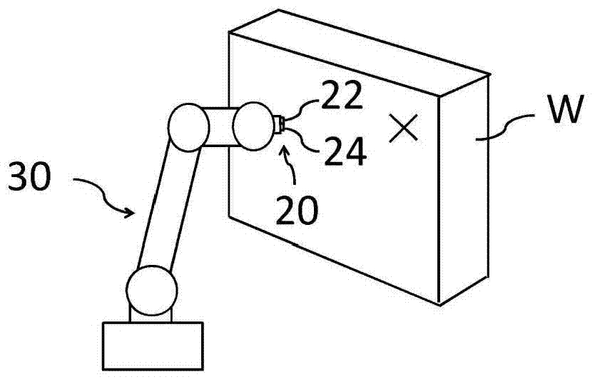
[0080] Figure 11 A schematic diagram of the robot system 10 of this embodiment is shown. Figure 11 The robot system 10 shown includes a plurality of robots 30 equipped with an imaging unit 20 and an end effector 110 for one workpiece W. In addition to this point, reference is made to Figure 8 ~ Figure 10 The robot system 10 described has the same structure, and redundant descriptions are omitted to avoid redundancy. In this way, a plurality of parts of the workpiece W can be imaged by a plurality of robots 30 equipped with the imaging unit 20 and the end effector 110 . Thereby, work (for example, machining) and measurement on the workpiece W can be performed in a short time.
[0081] In addition, in figure 1 In the illustrated robot system 10 , the distance of the workpiece W is measured and captured by one set of imaging units 20 and the robot 30 , but multiple sets of imaging units 20 and robots 30 may measure the distance of the workpiece W and capture the image. For...
PUM
 Abstract
Description
Claims
Application Information
 - R&D
- Intellectual Property
- Life Sciences
- Materials
- Tech Scout
- Unparalleled Data Quality
- Higher Quality Content
- 60% Fewer Hallucinations
Browse by: Latest US Patents, China's latest patents, Technical Efficacy Thesaurus, Application Domain, Technology Topic, Popular Technical Reports.
© 2025 PatSnap. All rights reserved.Legal|Privacy policy|Modern Slavery Act Transparency Statement|Sitemap|About US| Contact US: help@patsnap.com