Non-return valve for plasticizing screw of injection molding machine

A technology of plasticizing screw and locker, which is applied in the field of backflow locker for plasticizing screw of injection molding machine, which can solve the problems of high pressure, large shear heat, affecting the quality of plastic melt and injection molded parts, and achieve self-improvement Cleans, improves pressure reducing effect

Active Publication Date: 2013-03-27
ENGEL AUSTRIA
View PDF5 Cites 6 Cited by
  • Summary
  • Abstract
  • Description
  • Claims
  • Application Information

AI Technical Summary

Problems solved by technology

However, the disadvantage of this construction is that the plastic melt is squeezed during the metering process due to the small cross-sectional openings and gaps between the locking ring and the tip of the plasticizing screw, resulting in high pressures and large Shear heat, which negatively affects the quality of the plastic melt and thus of the later injection molded part

Method used


Image

  • Non-return valve for plasticizing screw of injection molding machine
  • Non-return valve for plasticizing screw of injection molding machine
  • Non-return valve for plasticizing screw of injection molding machine

Examples


Embodiment Construction

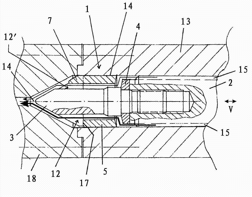
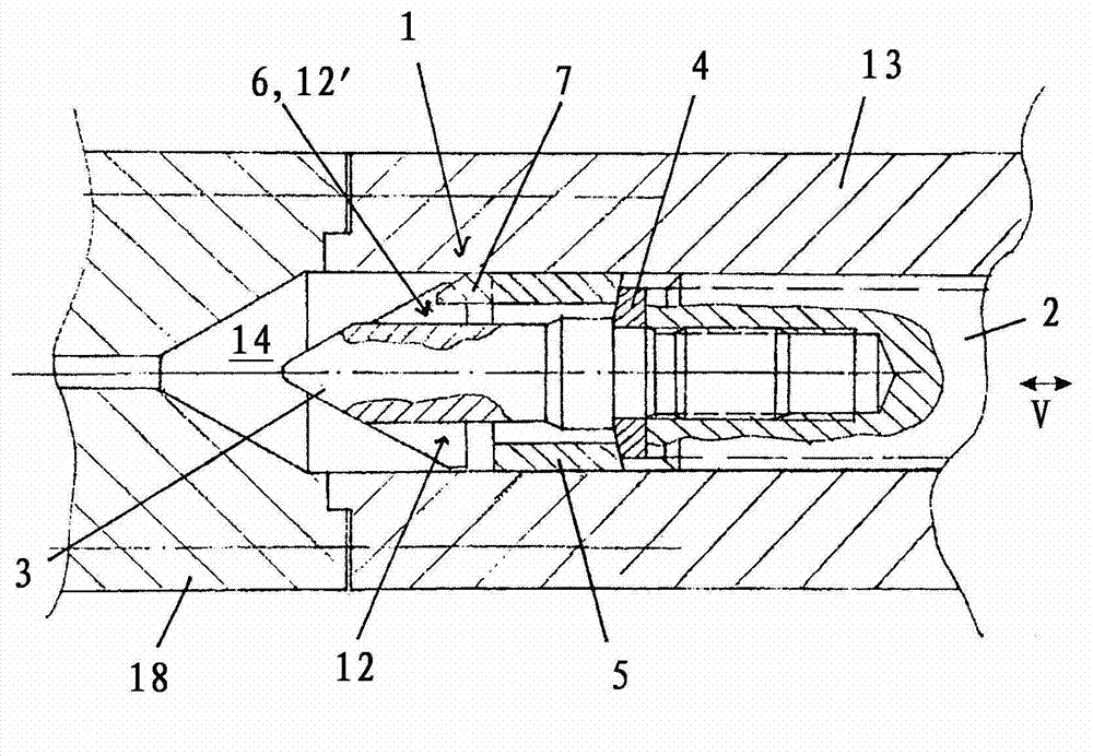
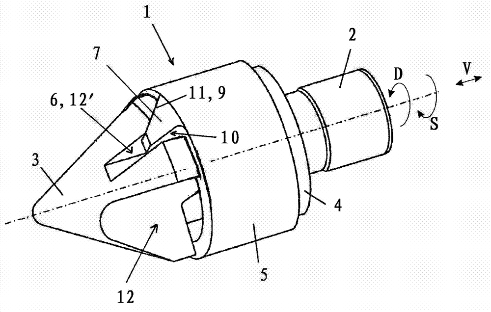
[0019] figure 1 The important parts of an injection molding machine for illustrating a first advantageous embodiment of the backflow lock 1 according to the invention are schematically shown in . Part of a plasticizing screw 2 can be seen, which is arranged rotatably and displaceably in a plasticizing cylinder 13 . Arranged on the tip 3 of the plasticizing screw 2 is a backflow lock 1 comprising a thrust ring 4 and a locking ring 5 arranged displaceably relative to the tip 3 and to the thrust ring 4 . The direction of movement of the locking ring 5 or of the plasticizing screw 2 is assigned the reference symbol V. The tip 3 has two guide rails 6 for the two carriers 7 arranged on the locking ring 5 and, in addition to the two guide rails 6 , four flow channels 12 and 12' for the plastic melt, wherein , only one of the two guide rails 6 and two of the four flow channels 12 and 12' can be seen in this figure. One of the visible flow channels, designated with the reference num...


PUM


Abstract

The invention relates to a non-return valve (1) for plasticizing the screw (2) of an injection molding machine, which comprises a tip (3), a pressure ring (4) and a locking ring (5) displaceably arranged relative to the tip (3) and the pressure ring (4). At least one guide rail (6) of at least one carrier (7) is arranged on the tip (3) or on the locking ring (5). The at least one guide rail (6) is provided with a wall (8) parallel to the displacement direction (V) of the locking ring (5) and a wall (9) obliquely arranged relative to the displacement direction (V) of the locking ring (5). the at least one carrier (7)is provided with parallelly extended sections (10, 11). The tip (3) is provided with at least one flow passage (12, 12') for plastic melt, besides the existing guide rail (6).

Description

technical field [0001] The invention relates to a backflow locker for plasticizing screw of injection molding machine, the backflow locker comprises a tip, a thrust ring and a locking ring movably arranged with respect to the tip and with respect to the thrust ring, wherein, at the tip In or on the locking ring there is provided at least one guide rail for at least one carrier arranged on the locking ring or on the tip, wherein the at least one guide rail has a wall arranged parallel to the direction of movement of the locking ring and an inclined A wall arranged in the direction of movement of the locking ring, and the at least one entraining element has a corresponding section extending in parallel. Furthermore, the use of the backflow lock according to the invention in a method for injecting a plastic melt into a cavity of an injection molding machine is to be provided. Background technique [0002] Backflow locks have a decisive influence on the quality of injection mol...

Claims


Application Information

Patent Timeline
Patent Type & Authority Applications(China)
IPC IPC(8): B29C45/52
CPCB29C45/52B29C31/04B29C45/20B29C45/70
Inventor M·施米德
Owner ENGEL AUSTRIA
Why Eureka
Try Eureka