

Injection moulding device
A technology for equipment and positioning elements, applied in the field of die-casting equipment, can solve problems such as installation difficulties, and achieve the effect of less workload and less labor-hour consumption
- Summary
- Abstract
- Description
- Claims
- Application Information
AI Technical Summary
Problems solved by technology
Method used
Image

Examples
Embodiment Construction
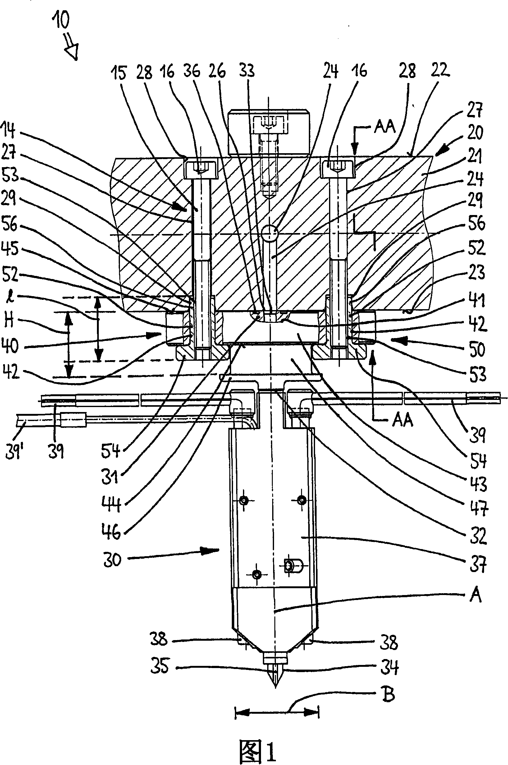
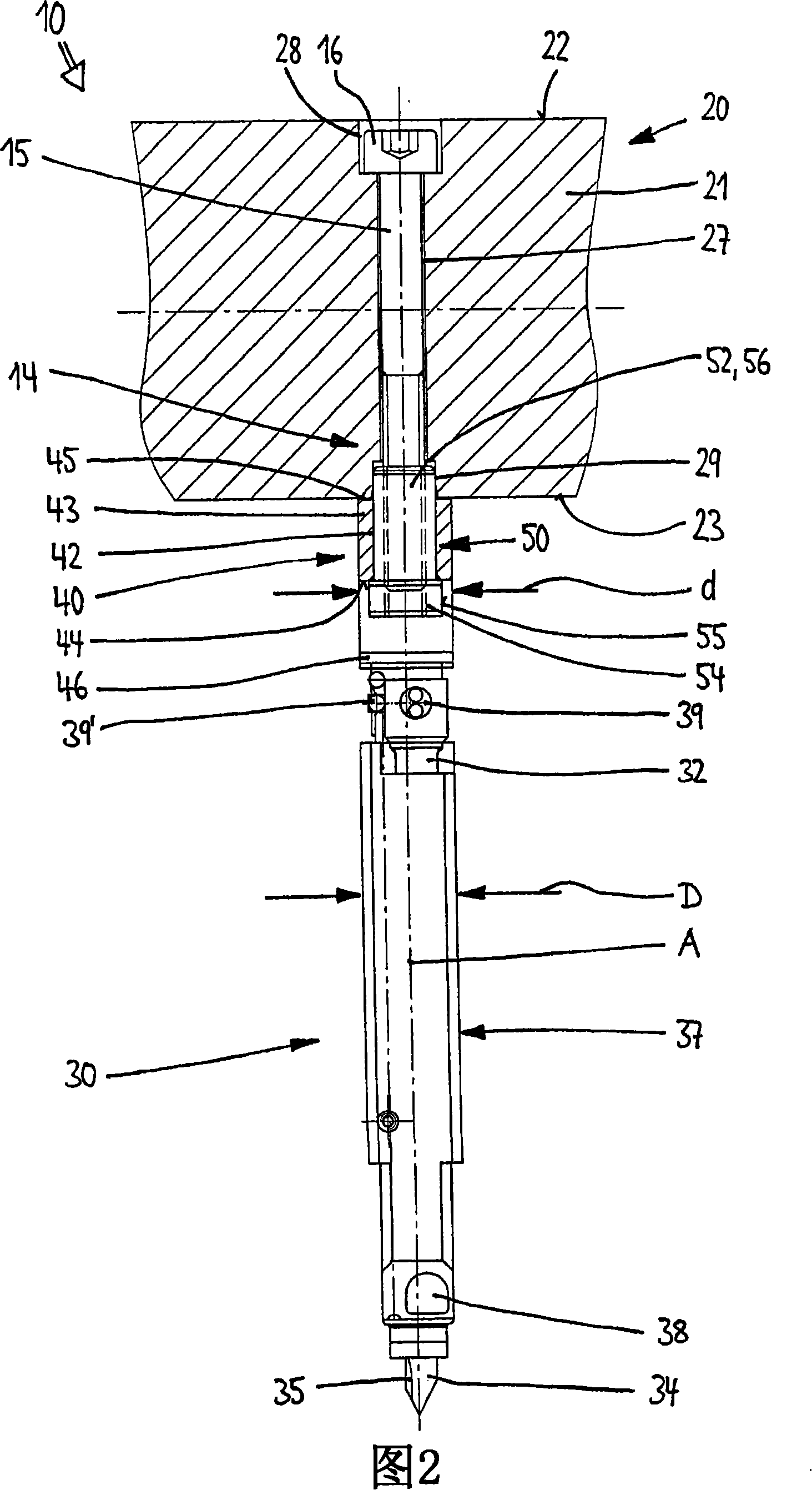
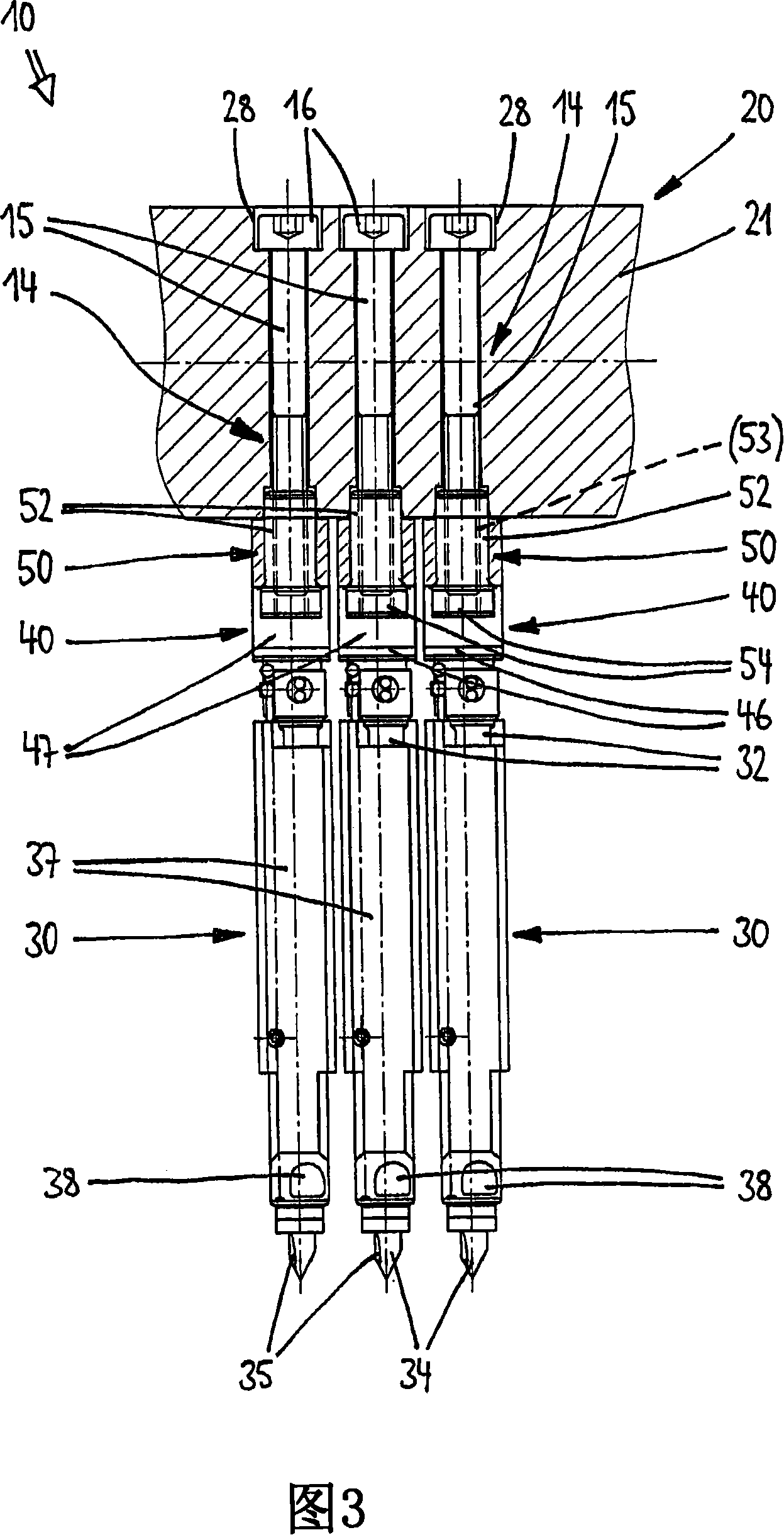
[0030] The die-casting plant indicated at 10 in FIG. 1 is used for processing molten material, for example plastic melt. In addition to other (not shown) components such as an introduction device for the material to be processed, a mold cavity plate with mold elements and the like, the die-casting plant has a temperature-controlled distributor 20 and at least one The hot-runner nozzles 30 mounted on the distributor 20 , wherein each hot-runner nozzle 30 can be fixed on the distributor 20 with a stop element 40 .
[0031] The distributor 20 is formed by a distribution disc 21 having a substantially planar top surface 22 and a substantially planar bottom surface 23 parallel thereto. A plurality of flow channels 24 leading to outlets 26 in the bottom 23 of the distribution disk 21 are provided in the distribution disk 21 . Two through holes 27 are arranged symmetrically about the outlet 26 in the distribution plate 21, and a stepped groove 28 is provided for the through holes 27...
PUM
 Abstract
Description
Claims
Application Information