Preparation method of composite material bar for concrete structure

A technology for concrete structures and composite materials, which is applied in the field of manufacturing composite material bars for concrete structures in the construction industry, can solve problems such as poor thermal expansion coefficient adaptability, etc., and achieve the effect of strong operability

Inactive Publication Date: 2013-03-27
WUHAN UNIV OF TECH
View PDF5 Cites 8 Cited by
  • Summary
  • Abstract
  • Description
  • Claims
  • Application Information

AI Technical Summary

Problems solved by technology

[0003] For some cases where the use environment is relatively harsh, single fiber or commonly used hybrid fiber reinforced composite bars are used to strengthen concrete. Since the thermal expansion coefficient of a single fiber is a certain value in the axial direction, the thermal expansion coefficient of single fiber reinforced compos

Method used


Image

  • Preparation method of composite material bar for concrete structure
  • Preparation method of composite material bar for concrete structure
  • Preparation method of composite material bar for concrete structure

Examples


Embodiment 1

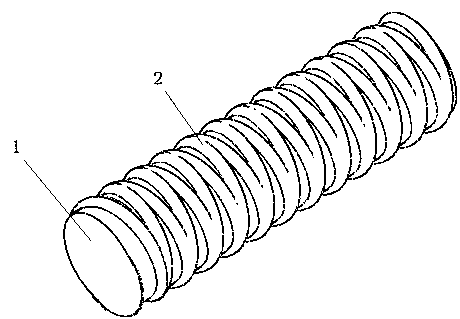
[0014] The total length of composite bars for a certain size of concrete is 1600mm, 30mm in diameter. Among them, the diameter of the glass fiber core is 26mm, and the height of the carbon fiber thread is 2mm. Pitch 8mm, Two strands of yarn are intertwined, such as image 3 . The preparation process is as follows: First, the resin-impregnated unidirectional glass fiber bundles are shaped by a mold with a diameter of 26 mm under tension; then, Before curing The surface is spirally wound with carbon fiber double-bundle yarns, the two bundles of yarns are crossed, the thickness of the yarn sheet is controlled to 2mm, and the winding parameters are adjusted to make the carbon fiber bundles press Pitch 8mm Winding to form threaded protrusions 2; finally, after curing together, cut to length 1600mm ie Get composite tendons.

Embodiment 2

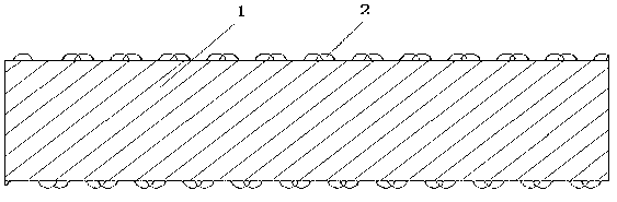
[0016] The total length of composite bars for a certain size of concrete is 2000mm , 20mm in diameter. Among them, the diameter of the glass fiber core is 16mm, the height of the carbon fiber composite thread is 2mm, the pitch is 5mm, and the single thread is wound, such as Figure 4 . The preparation process is as follows: First, the resin-impregnated unidirectional glass fiber bundles are drawn by a pulling force after being shaped by a mold with a diameter of 16mm; then, Before curing The surface is spirally wound with a single bundle of carbon fiber yarn, the thickness of the yarn sheet is controlled to 2mm, and the winding parameters are adjusted so that the carbon fiber bundle is wound with a pitch of 5mm to form a thread protrusion 2; finally, after curing together, intercept 2000mm The length is the composite material rib.


PUM

PropertyMeasurementUnit
Total lengthaaaaaaaaaa
Diameteraaaaaaaaaa
Diameteraaaaaaaaaa

Abstract

The invention provides a preparation method of a composite material bar for a concrete structure. The composite material bar consists of a one-way glass fiber composite material core and a carbon fiber spiral bulge. A preparation technology comprises the following steps of: firstly, under the traction of traction force, carrying out mould shaping on one-way glass fiber bundles soaked with resin to form the one-way glass fiber composite material core; secondly, spirally winding a carbon fiber composite material around the surface before curing, and adjusting winding parameters so as to wind one or more carbon fiber bundles by a certain thread pitch, thus forming a thread; and at last, carrying out curing on the composite core and the thread together and cutting out as required length, thus obtaining the composite material bar for the concrete structure. The coefficient of thermal expansion of the composite material bar is adjusted to be close to that of concrete by the composition of the carbon fiber composite material spiral outer layer and the glass fiber composite material core rod as well as the changes of the winding angle and the winding thread pitch of the carbon fiber, and the temperature stress of the composite material bar and the concrete is lowered.

Description

technical field [0001] The invention relates to a method for manufacturing composite material tendons for concrete structures in the construction industry. Background technique [0002] In the field of construction, reinforced concrete structures have been widely used. While meeting the requirements of industry and civil use, it also exposes the problem of insufficient durability when steel bars are used as the main tensile member. Composite materials (fiber reinforced plastics) FRP) has the advantages of light weight, high strength, corrosion resistance, thermal expansion coefficient similar to concrete, etc., and can be used with concrete at the same time, so FRP bars have received widespread attention. Composite bars are now generally made by pultrusion, and there are GFRP bars, CFRP bars, AFRP bars, and hybrid fiber composite bars on the market. Patent CN2632321Y discloses a preparation method of a composite material anchor rod, which relates to a composite material rod...

Claims


Application Information

Patent Timeline
IPC IPC(8): B29C70/52B29C70/32
Inventor 蔡浩鹏王钧王发洲程华
Owner WUHAN UNIV OF TECH
Why Eureka
Try Eureka