Pneumatic tire

A technology of pneumatic tires and tires, which is applied in the direction of off-road vehicle tires, tire parts, tire treads/tread patterns, etc., which can solve problems such as insufficient effects, and achieve improved soil removal performance, improved mud performance, and improved adhesion Effect

Active Publication Date: 2013-03-27
SUMITOMO RUBBER IND LTD
View PDF7 Cites 27 Cited by
  • Summary
  • Abstract
  • Description
  • Claims
  • Application Information

AI Technical Summary

Problems solved by technology

[0006] However, this proposal only stops at the improvement of the shoulder land

Method used


Image

  • Pneumatic tire
  • Pneumatic tire
  • Pneumatic tire

Examples


Embodiment Construction

[0036] Hereinafter, embodiments of the present invention will be described in detail.

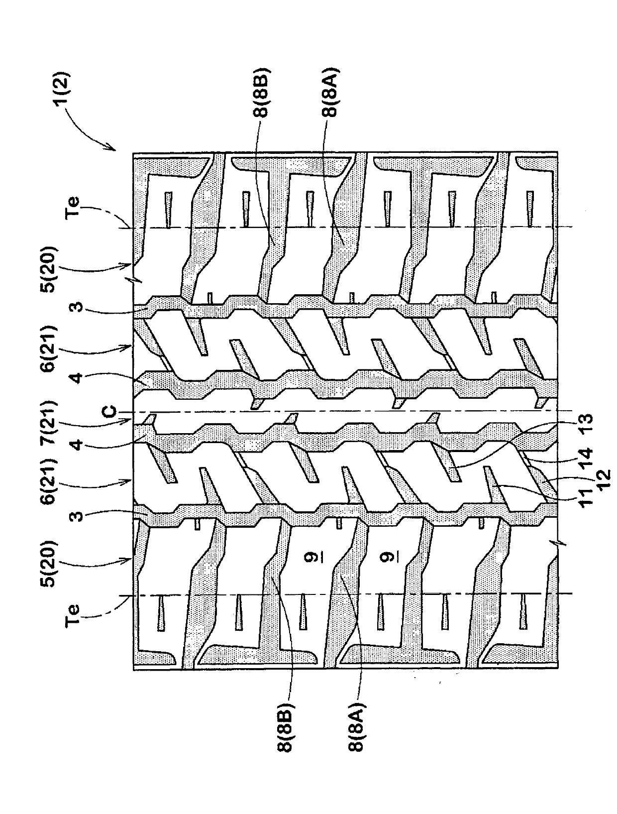
[0037] exist figure 1In the pneumatic tire 1 of this embodiment, the tread portion 2 is provided with a pair of shoulder main grooves 3 extending in the tire circumferential direction on the side closest to the tread edge Te, and a pair of shoulder main grooves between the pair of shoulder main grooves. 3. One or two crown main grooves 4 extending along the tire circumference. As a result, the shoulder land portion 5 is formed on the outside of the shoulder main groove 3 in the tire axial direction, and the middle land portion 6 is formed between the shoulder main groove 3 and the crown main groove 4 . In this example, a case where two crown main grooves 4 are provided is exemplified, and a crown land portion 7 is formed between the crown main grooves 4 , 4 .

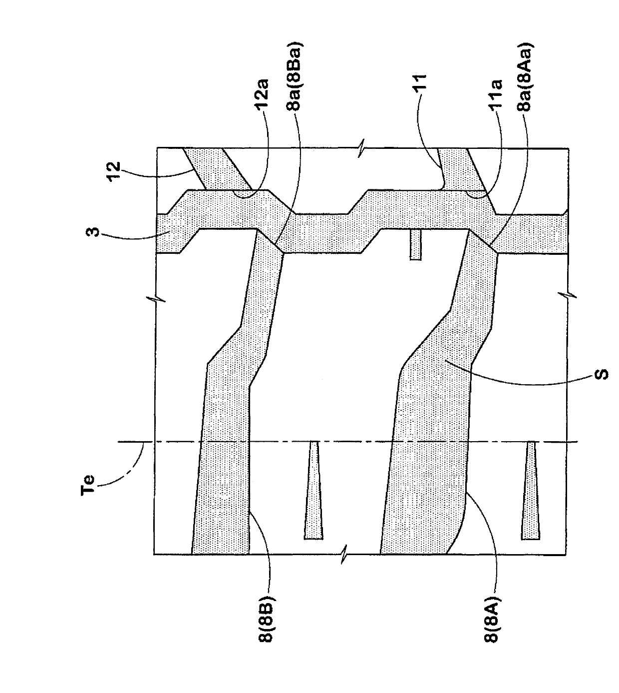
[0038] The shoulder land portion 5 is provided with shoulder lateral grooves 8 at intervals in the tire circumferential directio...


PUM


Abstract

A pneumatic tire comprises shoulder land zones and middle land zones divided by shoulder main grooves and a crown main groove. The shoulder land zone is divided by shoulder lateral grooves into shoulder blocks. The middle land zone is formed as a circumferential rib in substance. The middle land zone is provided with first and second middle outward slots which extend from the shoulder main groove toward the axially inside beyond the widthwise center line of the middle land zone, while gradually decreasing the width and inclining with respect to the tire axial direction at an angle [theta]1 and an angle [theta]2 ([theta]2>[theta]1), respectively, and terminate within the middle land zone. The open ends of the first and second middle outward slots respectively face the open ends of the shoulder lateral grooves at the shoulder main groove.

Description

technical field [0001] The present invention relates to a pneumatic tire that balances mud performance and noise performance. Background technique [0002] For tires installed on four-wheel drive vehicles that not only drive on paved urban ground, but also on uneven ground such as muddy ground, on the one hand, the so-called mud performance that exerts sufficient driving force on muddy ground is required. On the one hand, excellent noise performance such as quietness is required when driving on paved roads in urban areas. [0003] Furthermore, the following Patent Document 1 proposes a tire capable of achieving both the above-mentioned mud performance and noise performance. [0004] Such as Figure 6 As an example, the proposed tire has a shoulder land portion rs and a middle land portion rm divided by the shoulder main groove gs and the crown main groove gc, and the shoulder land portion rs is divided by the shoulder lateral groove ys to form Columns of shoulder block bs....

Claims


Application Information

Patent Timeline
IPC IPC(8): B60C11/03
CPCB60C2011/0365B60C2011/0388B60C11/0306B60C2011/0381B60C11/01B60C11/03B60C11/04B60C11/11B60C11/12B60C2011/0346B60C2011/0358B60C2200/14
Inventor 田麦显大
Owner SUMITOMO RUBBER IND LTD
Why Eureka
Try Eureka