
Mobile terminal support structure for saddle-riding vehicles

A technology for saddle-riding vehicles and mobile terminals, which is applied in the field of supporting structures of mobile terminals, can solve problems such as the inability to effectively use the seat space, and achieve the effects of simple structure, vibration attenuation, and vibration attenuation.

Active Publication Date: 2015-09-30
HONDA MOTOR CO LTD
View PDF6 Cites 0 Cited by
  • Summary
  • Abstract
  • Description
  • Claims
  • Application Information

AI Technical Summary

Problems solved by technology

[0004] However, in the above-mentioned conventional saddle-riding vehicle, there is a problem that the mobile terminal is stored and supported in the above-mentioned bag provided at the bottom of the storage box. When picking and placing the mobile terminal, the above-mentioned items must be picked and placed. In addition, even if the items are arranged under the mobile terminal, the mobile terminal must be avoided every time the item is picked and placed, and the vehicle seat under the seat cannot be effectively used. space

Method used


Image

  • Mobile terminal support structure for saddle-riding vehicles
  • Mobile terminal support structure for saddle-riding vehicles
  • Mobile terminal support structure for saddle-riding vehicles

Examples


no. 1 approach

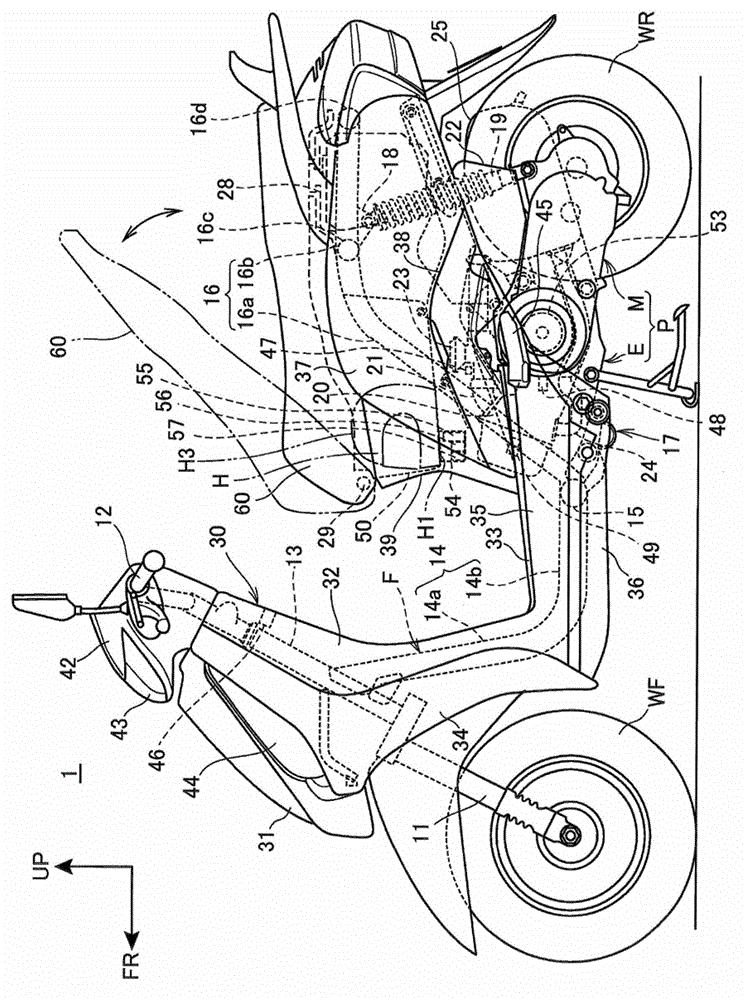
[0063] figure 1 It is a left side view of the motorcycle according to the first embodiment of the present invention.

[0064] like figure 1 As shown, the frame F of a scooter-type motorcycle 1 (saddle-riding vehicle) is configured to include: a head pipe 13 that steerably supports a pair of front forks 11 on which a front wheel WF is suspended; The main frame 14, the front end of which is combined with the head pipe 13; the cross pipe 15, which is provided at the rear of the main frame 14 and extends in the vehicle width direction; and a pair of left and right rear frames 16, 16 (only shown in the paper The front end portion of the rear frame 16 on this side is connected to both ends of the cross pipe 15 respectively. A rod-shaped handlebar 12 is connected to the upper portion of the front fork 11 .

[0065] The main frame 14 integrally has a down frame portion 14a inclined backward from the head pipe 13 and a down frame portion 14b extending rearward substantially horizont...

no. 2 approach

[0119] Below, refer to Figure 7 ~ Figure 9 A second embodiment to which the present invention is applied will be described. In this second embodiment, the same reference numerals are assigned to the same components as those in the above-mentioned first embodiment, and description thereof will be omitted.

[0120] In the above-mentioned first embodiment, the mobile terminal support portion 65 is arranged at a position in front of the top H3 of the helmet H, and the charging cable 100 is supported by the hook-shaped electric wire formed by protruding a part of the seat pan 62 downward. The case of the support portion 70 was described, but in the second embodiment, the mobile terminal support portion 265 is disposed at a rear position avoiding the top H3 of the helmet H, and the charging cable 100 is passed through the interior of the seat 260 for riding. It is different from the above-mentioned first embodiment in that it is supported in passing.

[0121] Figure 7 It is a c...


PUM


Abstract

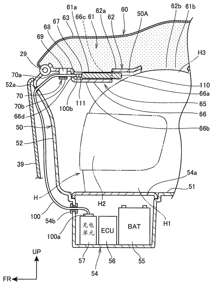
The invention relates to a mobile terminal supporting structure for a saddle-type vehicle, where a mobile terminal can be compactly received below a saddle of the saddle-type vehicle in such a manner that the space below the saddle is guaranteed and a received item is easy to fetch. The saddle-type vehicle comprises a receiving box (50) with an opening part at the upper side and a riding-purpose saddle (60) which covers the opening part and opens and closes the opening part. In addition, a mobile phone (110) is received in the space formed by the receiving box (50) and the riding-purpose saddle (6), in a manner of enabling power supply. On a saddle bottom plate (62) which supports a cushion part (61) of the riding-purpose saddle (60), a mobile terminal supporting part (65) for supporting the mobile phone (110) and an electric wire supporting part (70) for supporting a charging wire (100) of the mobile phone (110) are arranged.

Description

technical field [0001] The invention relates to a mobile terminal supporting structure of a saddle-riding vehicle. Background technique [0002] Conventionally, in a saddle-riding vehicle, a structure is known in which a waterproof bag having a power supply socket is provided at the bottom of the storage box under the seat, and a mobile terminal such as a mobile phone is connected to the power supply socket and stored in the above-mentioned bag. Inside the bag (for example, refer to Patent Document 1). [0003] Patent Document 1: (Japanese) Unexamined Patent Publication No. 2009-40087 [0004] However, in the above-mentioned conventional saddle-riding vehicle, there is a problem that the mobile terminal is stored and supported in the above-mentioned bag provided at the bottom of the storage box. When picking and placing the mobile terminal, the above-mentioned items must be picked and placed. In addition, even if the items are arranged under the mobile terminal, the mobile...

Claims


Application Information

Patent Timeline
Patent Type & Authority Patents(China)
IPC IPC(8): B62J1/28B62J9/00B62J11/19
Inventor 饭田王海安藤雅晴中野润一乾秀二郎藤原清隆
Owner HONDA MOTOR CO LTD
Learn More