Testing control device

A technology for testing control and testing signals, applied in the field of testing, can solve problems such as misoperation and inappropriate rotation force control, and achieve the effect of convenient installation and simple realization.

Inactive Publication Date: 2013-03-27
SIEMENS AG
View PDF4 Cites 6 Cited by
  • Summary
  • Abstract
  • Description
  • Claims
  • Application Information

AI Technical Summary

Problems solved by technology

[0004] In view of this, the present invention provides a test control device and method to solve the problem tha

Method used


Image

  • Testing control device
  • Testing control device
  • Testing control device

Examples


Embodiment Construction

[0052] In order to make the purpose, technical solution and advantages of the present invention clearer, the following examples are given to further describe the present invention in detail.

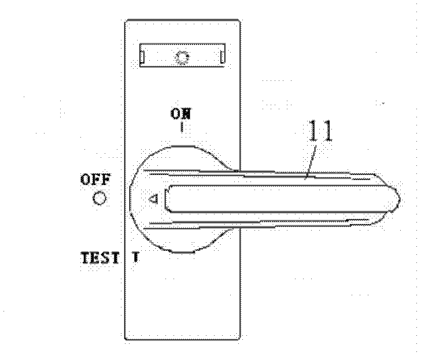
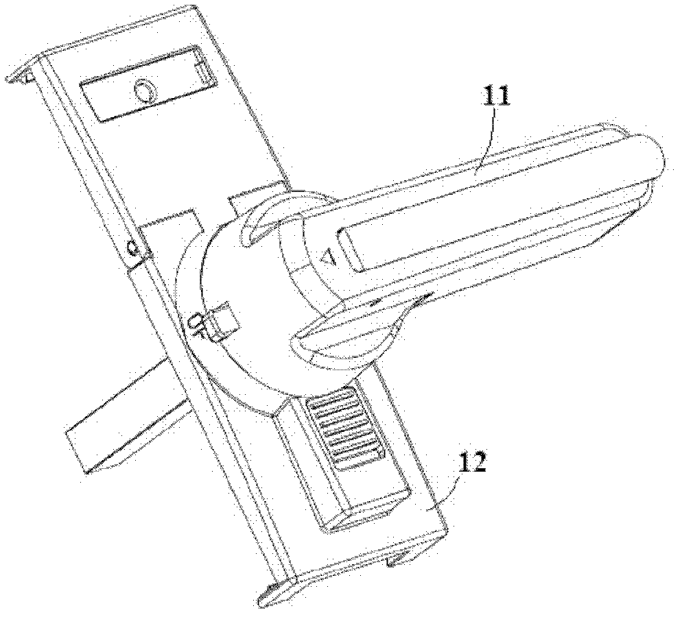
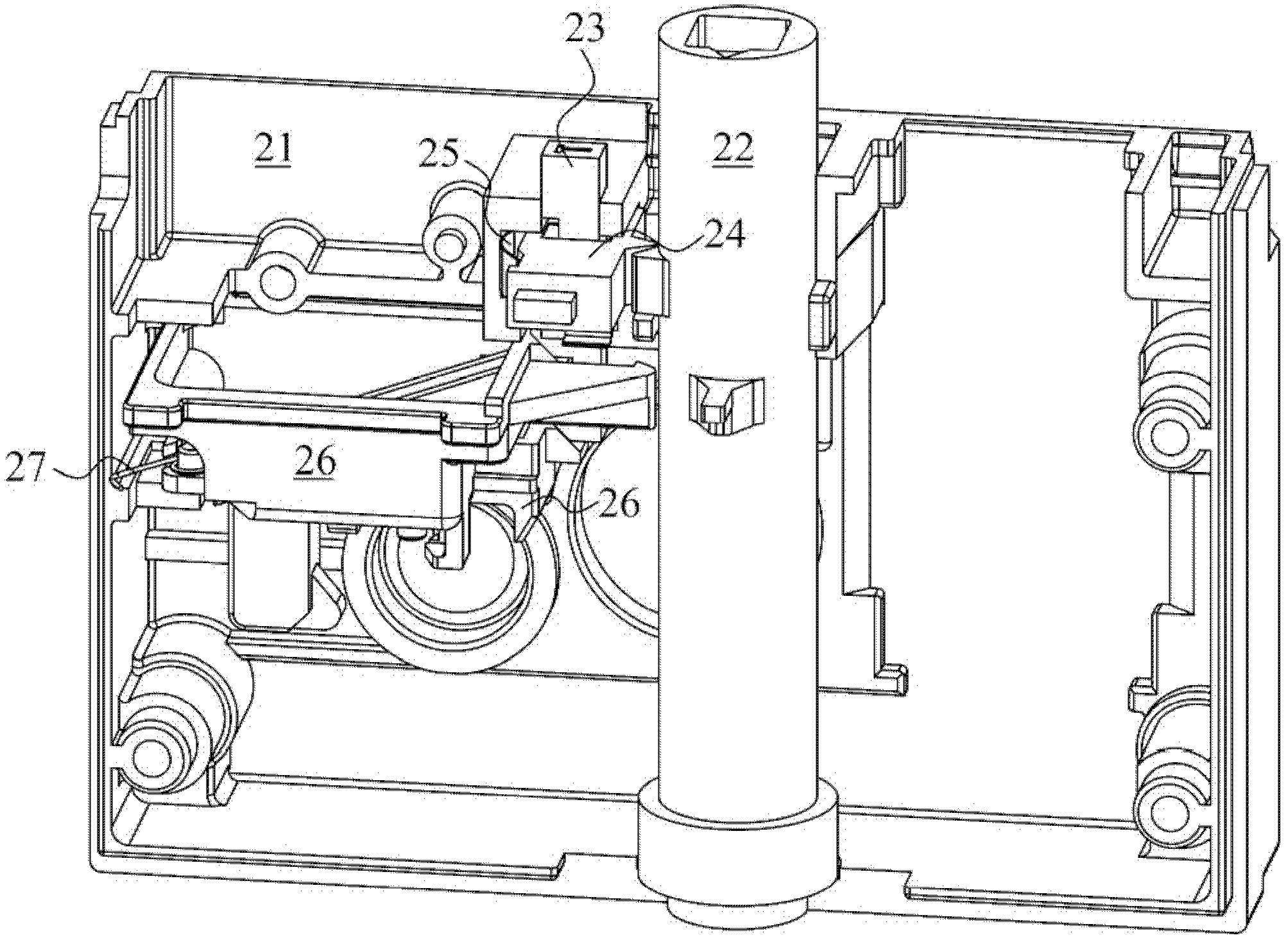
[0053]In order to avoid possible misoperation problems when the handle of the test control device has three operating positions: open, close and test, the embodiment of the present invention provides a test control device that uses buttons to control the test. The structure of the device is as follows: image 3 As shown, it includes: a housing 21, a drive shaft 22, a button 23, a locking slider 24, a first elastic member 25, an auxiliary part 26 and a second elastic member 27; the number of auxiliary parts 26 can be set to one or several, Such as image 3 The illustrated device auxiliary component 26 is specifically an auxiliary slider 26 , where two auxiliary sliders are provided as an example. in:

[0054] When the button 23 installed on the housing (21) is pressed, the auxiliary par...


PUM


Abstract

The invention discloses a testing control device. The testing control device comprises a casing (21), a driving shaft (22), a button (23), a locking slider (24), a first elastic member (25), an auxiliary part (26) and a second elastic member (27), the button (23) mounted on the casing (21) is pressed to push the auxiliary part (26) to move and trigger a testing signal switch to send a testing signal; the first elastic member (25) pushes the locking slider (24) to lock the button (23) at the position after the button (23) is pressed; the driving (22) mounted on the casing (21) is provided with a reset projection (221) which is used for pushing the locking slider (24) to reset when testing is finished and unlocking the button (23); and the second elastic member (27) is used for pushing the auxiliary part (26) to reset when the locking slider (24) is reset and pushing the button (23) to reset via the auxiliary part (26). The testing control device controls testing starting via the button, misoperation possibly existing via handle operation in the prior art is avoided, and reliability of testing control operation is improved.

Description

technical field [0001] The invention relates to the technical field of testing, in particular to a testing control device. Background technique [0002] Such as figure 1 As shown, in the prior art control device for implementing test control on equipment, the handle (Handle) 11 used for control operation has three position states: open position, closed position and test position. With this kind of control device, when the handle is rotated from the open position to the closed position, due to improper control of the rotation force, it is easy to cause the handle to go beyond the close position and rotate to the test position, resulting in some error signals and indications, which lead to The wrong operation is to start the test. [0003] In order to avoid this kind of misoperation, an existing solution is to set a screw. When the screw is installed, the handle can only be rotated to the open position and the closed position. When the screw is removed, the user is allowed t...

Claims


Application Information

Patent Timeline
IPC IPC(8): G01D11/20G01D11/16
Inventor 蒲恩强陈德州宋磊宋建康姜禹姜晓军胡彦涛周国标尹茂林
Owner SIEMENS AG
Why Eureka
Try Eureka