Mixing spray pipe runner wall face determination method, mixing spray pipe and supersonic speed mixing wind tunnel

A definite method and technology of mixed injection, which is applied in the direction of measuring devices, instruments, aerodynamic tests, etc., can solve the difficulty of analyzing experimental data, the quality of the flow field at the exit section of the mixing nozzle, and the inability to design the three-dimensional mixing channel for mixing efficiency and other issues to achieve the effect of improving the mixing efficiency

Active Publication Date: 2013-03-27
NAT UNIV OF DEFENSE TECH
View PDF8 Cites 21 Cited by
  • Summary
  • Abstract
  • Description
  • Claims
  • Application Information

AI Technical Summary

Problems solved by technology

[0007] At present, the existing nozzle design technology can only design two-dimensional or axisymmetric nozzles, and cannot design three-dimensional mixing channels with high mixing efficiency
In addition, if the start-up charact

Method used


Image

  • Mixing spray pipe runner wall face determination method, mixing spray pipe and supersonic speed mixing wind tunnel
  • Mixing spray pipe runner wall face determination method, mixing spray pipe and supersonic speed mixing wind tunnel
  • Mixing spray pipe runner wall face determination method, mixing spray pipe and supersonic speed mixing wind tunnel

Examples


Embodiment Construction

[0044] The embodiments of the present invention will be described in detail below with reference to the accompanying drawings, but the present invention can be implemented in many different ways defined and covered by the claims.

[0045] figure 1 is a schematic diagram of a supersonic mixing wind tunnel according to the present invention. Such asfigure 1 As shown, the supersonic mixing wind tunnel of the present invention includes a transition section 10 , a stabilization section 20 , a nozzle section 30 , an experiment section 40 , and a diffuser section 50 connected in sequence.

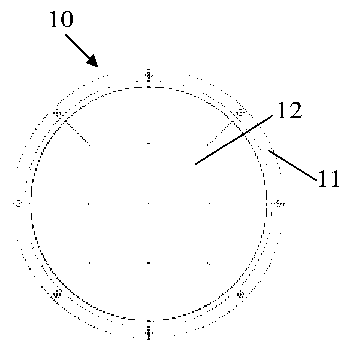
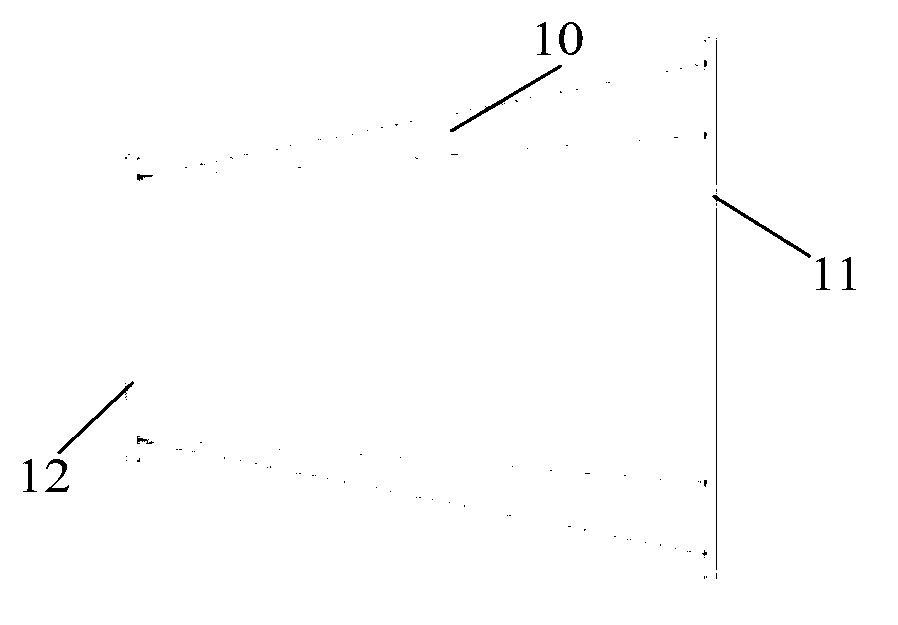
[0046] figure 2 and image 3 A schematic structure of a transition section of a supersonic mixing wind tunnel according to the present invention is shown. Such as figure 2 and image 3 As shown, the inlet 11 of the transition section 10 is circular and transitions to a square outlet 12 for preliminary rectification of the gas.

[0047] Figure 4 and Figure 5 A schematic structure of a s...


PUM


Abstract

The invention discloses a mixing spray pipe runner wall face determination method, a mixing spray pipe and a supersonic speed mixing wind tunnel. The mixing spray pipe runner wall face determination method includes following steps: providing a figure of an outlet section of a spray pipe to be determined and determining a circum-circle of the figure; taking the circum-circle as the outlet section of an imaginary round spray pipe, and determining a curve shaped surface of the round spray pipe by using a characteristics method; extracting filament line races of a runner according to the curve shaped surface of the round spray pipe; and determining filament lines in the filament line race corresponding to each point on the figure, wherein the filament lines of all points on the figure form a runner wall face of the spray pipe to be determined. According to the supersonic speed mixing wind tunnel, a three-dimensional mixing flow field is achieved, mixing efficiency is improved, quality of the flow field is comparable to quality of a two-dimensional flow field or an axisymmetric flow field, and a square outer spray pipe and a square experimental section facilitate implementation of observation technology.

Description

technical field [0001] The invention relates to a method for determining the flow channel wall surface of a nozzle, a mixing nozzle obtained by the determining method and a supersonic mixing wind tunnel with the mixing nozzle. Background technique [0002] The study of supersonic mixed flow field is a hot and difficult issue in modern aerodynamics research, which widely exists in flow fields such as scramjet engines, supersonic ejectors, air curtain cooling optical windows of high-speed missiles, and aerodynamic windows of high-energy lasers. The problems involved in flow stability, transition, vortex structure interaction and turbulence are far more complicated than incompressible mixed flow field, and have important engineering and theoretical value, and related research needs to be carried out in depth. [0003] A supersonic mixing wind tunnel is a necessary experimental device for generating a supersonic mixing flow field. Generally, two supersonic nozzles are used to g...

Claims


Application Information

Patent Timeline
IPC IPC(8): G01M9/04G01M9/02
Inventor 赵玉新赵延辉马志成
Owner NAT UNIV OF DEFENSE TECH
Why Eureka
Try Eureka