

Iron core fixing structure of disc type motor
A technology of fixed iron core and disc motor, applied in the direction of magnetic circuit shape/style/structure, magnetic circuit static parts, etc., can solve the problem of high welding process requirements, affecting motor performance, motor iron core and motor end cover fixing Difficulty and other issues
- Summary
- Abstract
- Description
- Claims
- Application Information
AI Technical Summary
Problems solved by technology
Method used
Image

Examples
Embodiment 1
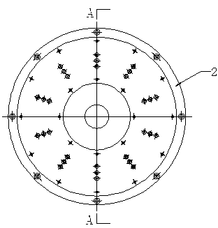
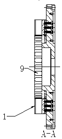
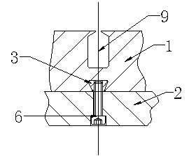
[0020] Such as figure 1 , figure 2 , image 3 , Image 6 As shown, the disc motor iron core fixing structure of the present invention includes a stator iron core 1 and an end cover 2 fixedly installed on the end surface of the stator iron core. The end surface of the stator iron core 1 is provided with a number of radially arranged dovetail grooves. 3. The number of dovetail grooves 3 is set according to the specific use requirements, at least two. In order to ensure the reliability of the connection, it can be set to multiple. The dovetail groove 3 is provided with a metal connection block 4 that can cooperate with the dovetail groove. The metal connection block 4 is set as a dovetail structure 7 that can be matched with the dovetail groove 3. The metal connecting block 4 is provided with a threaded hole 5 for connecting with the fastener on the end cover. After the metal connecting block 4 is inserted into the dovetail groove 3 The fastener 6 is connected with the thread...
Embodiment 2
[0022] Such as Figure 4 , Figure 7 As shown, the disc motor iron core fixing structure of the present invention includes a stator iron core 1 and an end cover 2 fixedly installed on the end surface of the stator iron core. The end surface of the stator iron core 1 is provided with a number of radially arranged dovetail grooves. 3. The number of dovetail grooves 3 is set according to the specific use requirements, at least two. In order to ensure the reliability of the connection, it can be set to multiple. The dovetail groove 3 is provided with a metal connection block 4 that can cooperate with the dovetail groove. The metal connection block 4 includes a dovetail structure 7 that can be matched with the dovetail groove 3 and a mounting block 8 located outside the dovetail groove 3. The mounting block 8 is provided with a threaded hole 5 for connecting with the fastener on the end cover 2, and the metal connection After the dovetail structure 7 of the block 4 is inserted int...
Embodiment 3
[0024] Such as Figure 5 , Figure 8 As shown, the disc motor iron core fixing structure of the present invention includes a stator iron core 1 and an end cover 2 fixedly installed on the end surface of the stator iron core. The end surface of the stator iron core 1 is provided with a number of radially arranged dovetail grooves. 3. The location of the dovetail groove 3 can be opposite to the position of the winding groove 9. The number of dovetail grooves 3 is set according to the specific use requirements, at least two. In order to ensure the reliability of the connection, it can be set to multiple. There is a metal connection block 4 that can be matched with the dovetail groove, and the metal connection block 4 includes two dovetail-shaped structures oppositely arranged, one of which can be matched with the dovetail groove 3, and the other dovetail-shaped structure can be connected with the end cover 1 In cooperation, the two dovetail structures are respectively inserted i...
PUM
 Abstract
Description
Claims
Application Information