
Rock debris automatic detection system and method

A technology for automatic detection and cuttings, which is applied to measurement devices, material analysis and instruments by observing the impact on chemical indicators, which can solve the problem of low degree of automation, increase the manual workload of detection and analysis, and fail to solve the problem of automation. and other problems, to achieve the effect of increasing the overall detection accuracy, increasing the image coverage, and reducing the work intensity

Inactive Publication Date: 2020-12-15
SUZHOU CASIA ALL PHASE INTELLIGENCE TECH CO LTD
View PDF28 Cites 0 Cited by
  • Summary
  • Abstract
  • Description
  • Claims
  • Application Information

AI Technical Summary

Problems solved by technology

[0003] Chinese patents CN201826835U and CN201522431U both disclose rock debris image acquisition devices, including the design of light source and stage, forming professional image acquisition equipment, combined with high-resolution camera / camera under the illumination of white light and fluorescent light source, it can better feedback rock debris. However, the above-mentioned technical solutions are not highly automated and lack the link of dry and wet judgment, which increases the manual workload of detection and analysis, and traditional cameras and light sources cannot provide good resolution and efficient discrimination speed
Chinese patent CN110873705A adopts the method of fluorescence combined with electron microscope scanning, combined with the lifting mechanism to improve the image acquisition accuracy and image information content, but this method still does not solve the problem of automation

Method used


Image

  • Rock debris automatic detection system and method
  • Rock debris automatic detection system and method
  • Rock debris automatic detection system and method

Examples


Embodiment Construction

[0036] In the description of the present invention, it should be noted that the terms indicating orientation or positional relationship are all based on the orientation or positional relationship shown in the drawings, or the orientation or positional relationship that is usually placed when the product of the invention is used. Such terms are only for the convenience of describing the present invention and simplifying the description, rather than indicating or implying that the referred device or element must have a specific orientation, be constructed and operated in a specific orientation, and thus should not be construed as limiting the present invention.

[0037] It should also be noted that, in the description of the present invention, unless otherwise clearly stipulated and limited, the terms "setting", "installation", "connection", "connection" and the like should be understood in a broad sense, for example, it may be a fixed connection , can also be detachably connecte...


PUM


Abstract

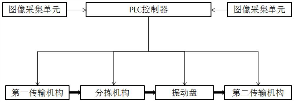
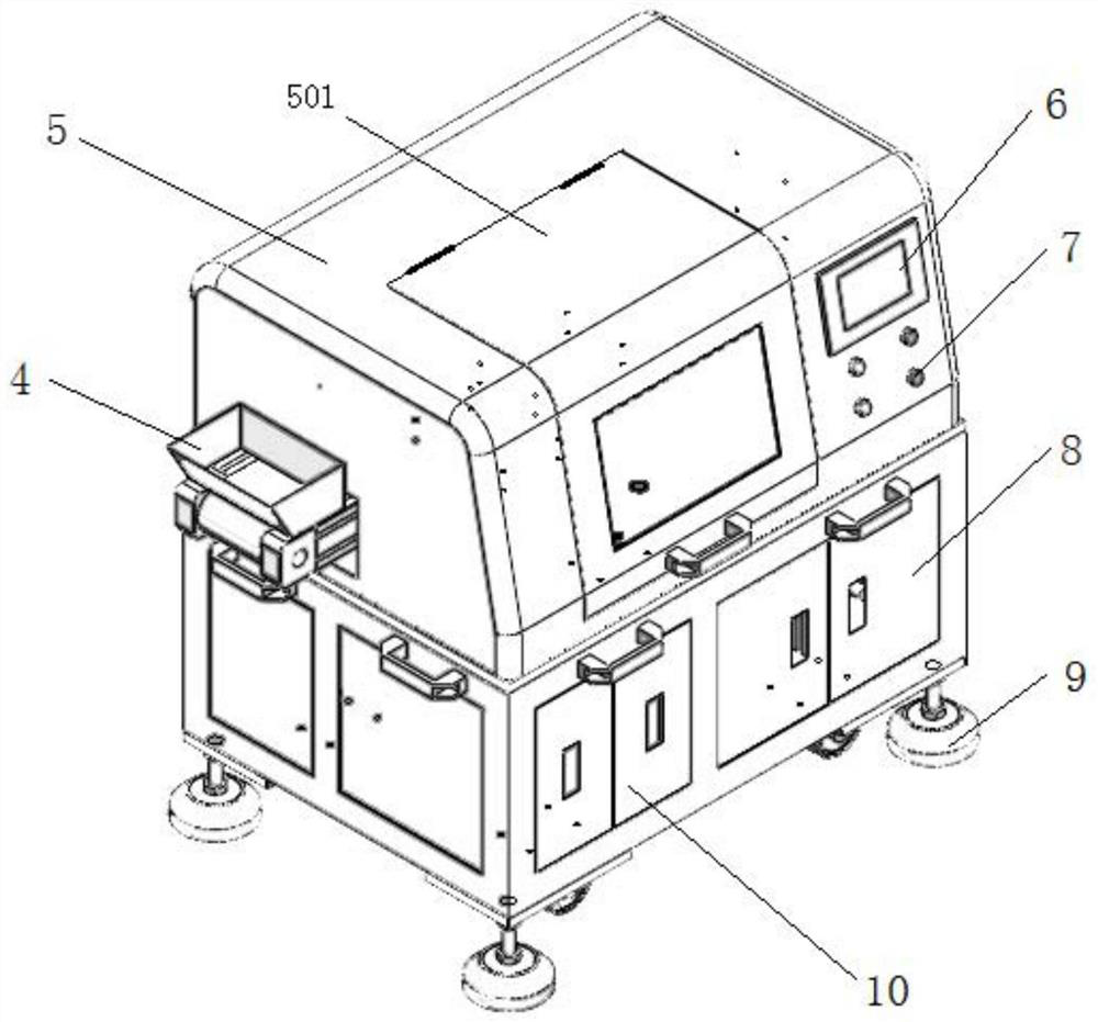
The invention discloses a rock debris automatic detection system and method. The system comprises an image acquisition unit, a sorting mechanism, a vibration disc, a transmission mechanism and a PLC.The image acquisition unit is erected above the transmission mechanism; the sorting mechanism and the vibration disc are connected in series in the transmission mechanism; and the PLC is connected with the transmission mechanism, the sorting mechanism, the vibration disc and the image acquisition unit. The method comprises the steps that rock debris is guided into the transmission mechanism, dry and wet materials are distinguished and sorted through image acquisition, the dry materials are dispersed and flattened, image acquisition is conducted again, and then high-fidelity and high-definitionimages are obtained and uploaded for analysis. Through the image acquisition unit and the sorting mechanism, higher-degree automation is realized, and the working intensity of technicians is reduced;and in addition, the problem of rock debris flattening is solved through the arranged vibration disc, high-fidelity and high-reduction rock debris surface images are provided in combination with post-processing of the intelligent camera, and the overall detection precision is improved.

Description

technical field [0001] The invention relates to the technical field of cuttings logging, in particular to a system and method for automatic detection of cuttings. Background technique [0002] In the existing technology, the real-time identification of cuttings at the mud logging site mainly relies on manual methods, that is, the cuttings samples brought out by drilling are regularly fished out of the mud, washed and dried, and judged by the naked eye of geological staff under a microscope. This traditional The current cuttings logging method has artificial subjectivity, and with the rapid development of drilling technology, the drilling speed is getting faster and faster, and the cuttings particles are getting finer, so the efficiency of manual identification cannot meet the logging requirements in the new situation. Because of this, cuttings imaging technology has gradually emerged in the domestic mud logging field in recent years. At present, most of the cuttings digital...

Claims


Application Information

Patent Timeline
Patent Type & Authority Applications(China)
IPC IPC(8): G01N21/78G01N21/01B07C5/34
CPCB07C5/34G01N21/01G01N21/78G01N2021/0112
Inventor 严柏林汪雪林郭晓锋
Owner SUZHOU CASIA ALL PHASE INTELLIGENCE TECH CO LTD
Learn More