Miniature driving motor

A technology of miniature drive motor and leaf spring, used in electrical components, electromechanical devices, etc., can solve the problems of inability to guarantee the bonding strength, low processing accuracy, and cannot be used for positioning, etc., to improve the linear driving effect and increase the impact resistance performance. , the effect of improving the pass rate

Inactive Publication Date: 2013-03-27
深圳市光控数码光电有限公司
View PDF5 Cites 0 Cited by
  • Summary
  • Abstract
  • Description
  • Claims
  • Application Information

AI Technical Summary

Problems solved by technology

[0004] The difficulty brought about by this method is: in order to ensure the consistency of elastic deformation, it is necessary to strictly control the distance between the outer ring of the upper spring leaf and the outer edge of the lower spring leaf, and the distance between the inner ring of the upper spring leaf and the inner edge of the lower spring leaf; Since the inner ring of the upper spring is fixed on the top of the carrier, and the inner edge of the lower spring is fixed on the bottom of the carrier, both are fixed on the same part, so it is only necessary to ensure the processing accuracy of the carrier, that is, the inner ring of the upper spring and the inner ring of the upper spring can be easily controlled. The spacing between the inner edges of the lower shrapnel; however, the outer ring of the upper spring leaf and the outer edge of the lower shrapnel are respectively fixed on different parts, and the thicker part between the two is the magnet assembly, but the magnet assembly itself The processing accuracy is low and the error is large, so it cannot be used to locate the distance between the two; in addition, in traditional products, the outer ring of the upper spring and the upper gasket are fixed on the upper cover, and the installation position is limited by the accuracy and fixing method of the upper cover; The outer edge of the lower shrapnel is crimped and fixed on the base by the lower gasket, and its installation position is limited by the accuracy of the base and the fixing method; finally, the upper cover is glued and fixed on the base, so it is difficult to accurately ensure the distance between the outer ring of the spring leaf and the outer edge of the lower shrapnel That is, it is difficult to ensure that the elastic deformation produced by the upper spring and the lower spring just offsets the gravity produced by the carrier and the lens, thus affecting the linear drive effect
[0005] In addition, in traditional products, each magnet in the magnet assembly is fixed by glueing its outer wall adjacent to the side wall of the upper cover to the side wall of the upper cover. The bonding effect cannot be known through direct observation, so the bonding cannot be guaranteed. As a result, in the drop test, due to the severe impact force, once the bonding strength of the magnet is slightly poor, it will loosen or even fall off from the side wall of the upper cover, resulting in defective products, so its structure also needs improvement. place

Method used


Image

  • Miniature driving motor
  • Miniature driving motor
  • Miniature driving motor

Examples


Embodiment 1

[0024] (Embodiment 1, micro drive motor)

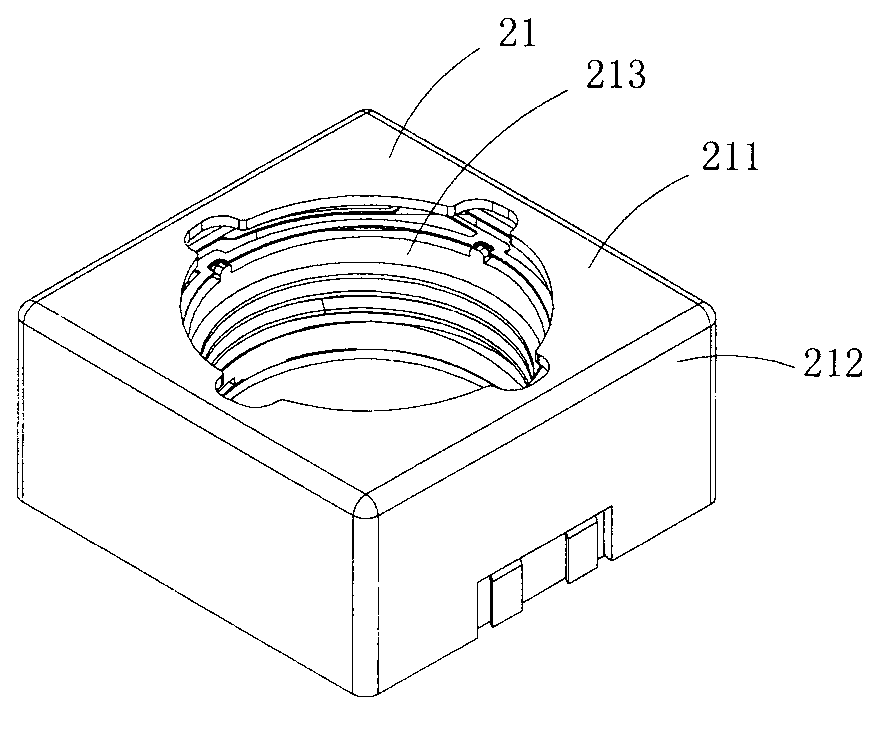
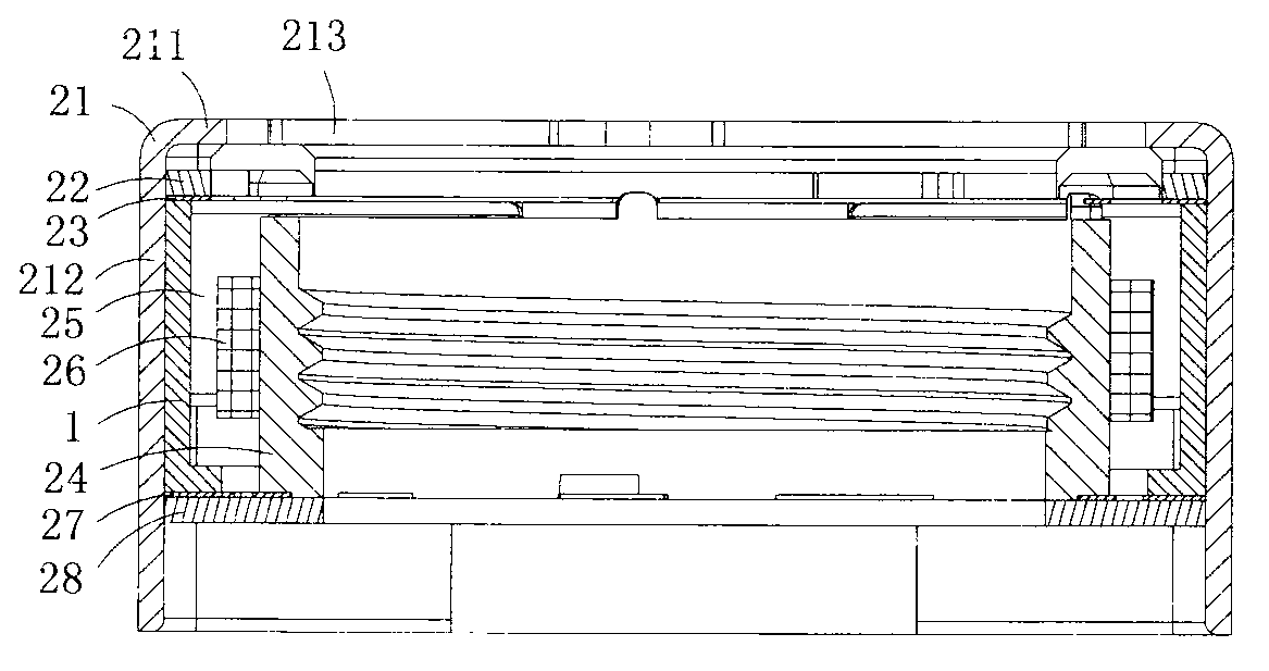
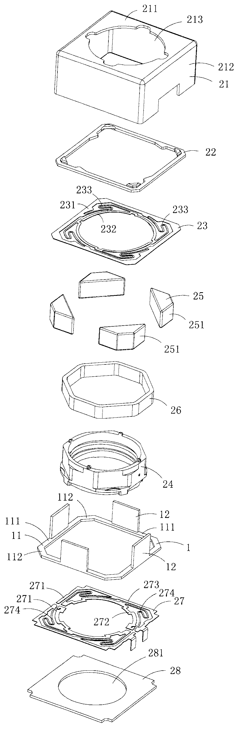
[0025] Figure 1 to Figure 3 Shows the first specific implementation of the micro drive motor of the present invention, wherein figure 1 It is a schematic diagram of a three-dimensional structure of the first structure of the micro drive motor of the present invention; figure 2 yes figure 1 A cutaway view of the micro drive motor shown; image 3 yes figure 1 An exploded view of the miniature drive motor shown.

[0026] Present embodiment is a kind of micro-drive motor for linearly driving micro-lenses, see Figure 1 to Figure 3 As shown, it includes a positioning bracket 1 , an upper cover 21 , an upper gasket 22 , an upper spring piece 23 , a carrier 24 , a magnet assembly 25 , a coil assembly 26 , a lower spring assembly 27 and a base 28 . The positioning bracket 1 is made of insulating plastic, and the upper cover 21 is made of magnetically conductive material.

[0027] The upper cover 21 includes a top wall 211 and a side ...

Embodiment 2

[0036] (Embodiment 2, miniature drive motor)

[0037] Figure 4 It is an exploded view of the second structure of the micro drive motor of the present invention, showing the second specific implementation of the micro drive motor of the present invention.

[0038] This embodiment is a micro drive motor made by the above-mentioned embodiment 1, which is basically the same as that of embodiment 4, except that the magnet assembly 25 includes four cuboid magnets 251, and each magnet 251 is adjacent to the upper cover correspondingly. One of the side walls 212 is set, that is, it is set in parallel with the corresponding one of the side walls 212; so in order to cooperate with this kind of magnet assembly, each support boss (12) in the positioning bracket 1 is located at two adjacent pressing edges ( 111), so that it is in the gap between two adjacent magnets 251.

Embodiment 3

[0039] (Embodiment 3, miniature drive motor)

[0040] Figure 5 and Figure 6 Shows the third embodiment of the micro drive motor of the present invention, wherein Figure 5 It is a cross-sectional view of the third structure of the micro drive motor of the present invention; Figure 6 yes Figure 5 A schematic diagram of a three-dimensional structure of the positioning bracket in the micro drive motor shown

[0041] This embodiment is basically the same as Embodiment 1, except that the base 28 is made of insulating plastic and has a central hole 281, and the plate-shaped body 11 of the positioning bracket 1 presses the outer edges 273 of the two elastic pieces 271. Connected and fixed on the insulating base 28.


PUM


Abstract

The invention discloses a miniature driving motor which comprises an upper cover, an upper gasket, an upper spring strip, a carrier, a magnet assembly, a coil assembly, a lower spring assembly, a positioning support and a base. The positioning support comprises a platy body and a plurality of supporting bosses, a through hole is arranged in the center of the platy body, the supporting bosses are protruded from the platy body and are positioned on the same side of the platy body, outer edges of two lower spring strips are in compression joint on the base fixedly by the platy body, and the supporting bosses are jacked on an outer ring of the upper spring strip. The miniature driving motor has the advantages that the distance from the outer ring of the upper spring strip to the outer edge of each lower spring strip can be effectively controlled, and accordingly a linear driving effect is improved.

Description

technical field [0001] The invention belongs to the technical field of micro-motor structure design, and in particular relates to a micro-drive motor. Background technique [0002] Micro camera devices have been widely used in mobile phones and notebook computers, and the micro drive motors (also called lens drive motors) therein are getting smaller and smaller. [0003] A traditional miniature drive motor generally includes an upper cover, an upper gasket, an upper spring sheet, a lens carrier, a magnet assembly, a coil assembly, a lower gasket, a lower spring assembly and a base. The traditional upper cover is made of magnetically permeable material, and includes a top wall and a side wall connected to the top wall, and a light-transmitting hole is arranged in the center of the top wall. The upper spring sheet includes an outer ring, an inner ring and a wire spring connecting the outer ring and the inner ring; the outer ring of the upper spring sheet is glued and fixed on...

Claims


Application Information

Patent Timeline
IPC IPC(8): H02K33/18
Inventor 胡小青
Owner 深圳市光控数码光电有限公司
Why Eureka
Try Eureka