Miniature drive motor

A micro-drive and motor technology, applied in electrical components, electromechanical devices, etc., can solve the problems of low production efficiency, high defect rate, cumbersome installation and manufacturing, etc. The effect of driving the effect

Inactive Publication Date: 2015-03-11
深圳市光控数码光电有限公司
View PDF4 Cites 0 Cited by
  • Summary
  • Abstract
  • Description
  • Claims
  • Application Information

AI Technical Summary

Problems solved by technology

[0004] This kind of traditional micro-drive motor is cumbersome to install and manufacture, with low production efficiency and high defective rate

Method used


Image

  • Miniature drive motor
  • Miniature drive motor
  • Miniature drive motor

Examples


Embodiment 1

[0020] (Embodiment 1, micro drive motor)

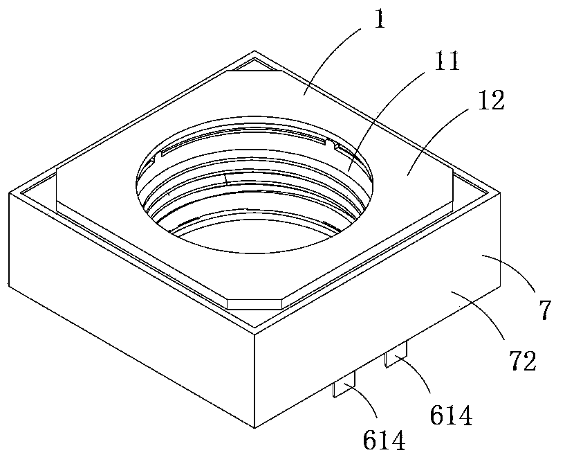
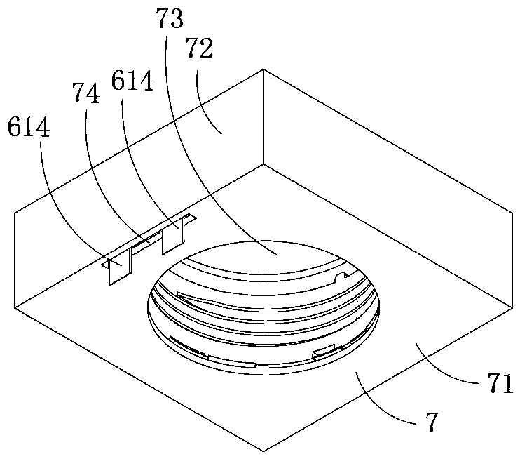
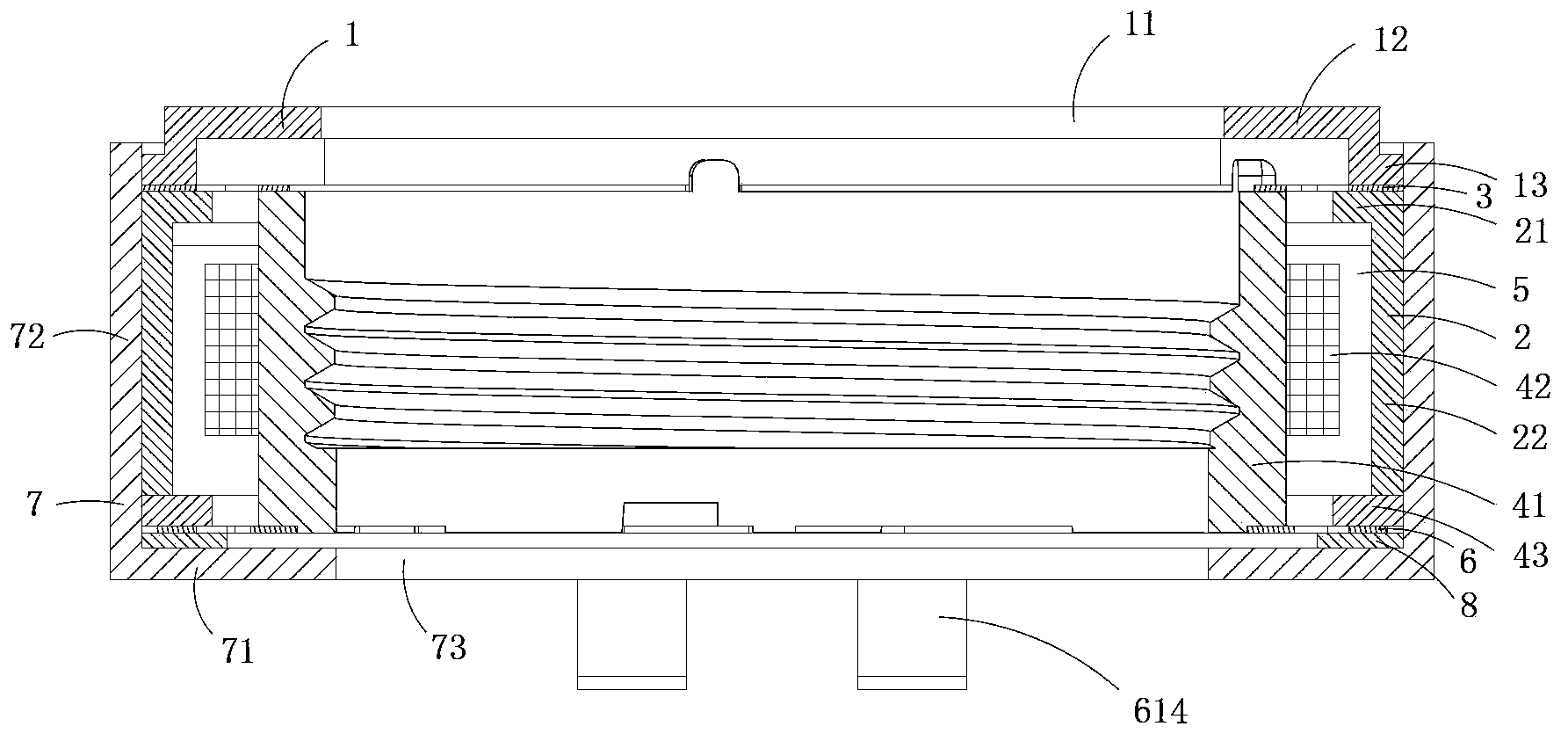
[0021] Figure 1 to Figure 5 A specific embodiment of the micro drive motor in the present invention is shown, wherein, figure 1 It is a schematic diagram of a three-dimensional structure of the first structure of the present invention; figure 2 yes figure 1 A schematic diagram of the three-dimensional structure of the micro-drive motor when viewed from another angle; image 3 yes figure 1 A cutaway view of the micro drive motor shown; Figure 4 yes figure 1 An exploded view of the micro-drive motor shown; Figure 5 yes figure 1 An exploded view of the miniature drive motor shown when viewed from another angle.

[0022] Present embodiment is a kind of miniature drive motor that drives miniature camera lens assembly, see Figure 1 to Figure 5 As shown, it includes an upper cover 1, an upper gasket 2, an upper spring sheet 3, a lens carrier 41, a magnet assembly 5, a coil assembly 42, a lower gasket 43, a lower spring sheet as...

Embodiment 2)

[0027] Figure 6 It is a cross-sectional view of the second structure of the present invention, showing the second specific implementation manner of the present invention.

[0028] This embodiment is basically the same as Embodiment 1, the difference is: see Figure 6 As shown, in this embodiment, no crimping boss 13 is provided at the bottom of the upper cover plate 12, but a frame-shaped pressing plate 9 is provided between the upper cover 1 and the outer ring 31 of the upper spring leaf 3, the upper cover 1 The cover 1 is crimped on the pressing plate 9 , and then the outer ring 31 of the upper spring piece 3 is crimped on the frame-shaped plate body 21 of the upper gasket 2 .

[0029] In addition, the upper cover 1 in this embodiment is made of non-magnetic material, and the base 7 is made of magnetic material. In this structure, a magnetic circuit passing through the coil assembly 42 is generated between the side of each magnet 51 close to the coil assembly 42 and the b...

Embodiment 3)

[0031] This embodiment is basically the same as Embodiment 1, except that the upper cover 1 and the base 7 in this embodiment are both made of magnetically permeable materials. This structure can effectively improve the utilization efficiency of the magnetic field of the magnet assembly, and can provide a more constant magnetic field for the coil assembly when the coil assembly moves with the carrier, thereby effectively improving the linear driving effect.

[0032] It can be seen from the above embodiments 1 to 3 that when the present invention is assembled, it only needs to be installed and fixed one by one in the order of first down and then up, and its process and operation are relatively simple; The special shape structure can accurately control the distance between the outer ring of the upper spring piece and the outer edge of the lower spring piece, so as to effectively ensure that the elastic deformation of the upper spring piece and the lower spring piece just offsets ...


PUM


Abstract

The invention discloses a miniature drive motor which comprises an upper cover, an upper gasket, an upper spring leaf, a lens carrier, a magnetic component, a coil component, a lower gasket, a lower spring leaf component, a base and an insulating gasket. The base comprises a bottom wall and a side wall protruding upwards. The bottom wall is provided with a central hole. The base is provided with a wiring hole. The outer rings of the two spring leaves are pressed and fixed on the insulating gasket through the lower gasket, so that the insulating gasket is pressed and fixed on the bottom wall of the base. Conducting pins of the lower spring leaves exposes from the base wiring hole of the base. The upper gasket comprises a frame plate body and a support plate protruding from the plate body and extending towards the lower gasket. The support plate is butted against the lower gasket. The upper cover comprises a cover plate with a light permeating hole. The outer ring of the upper spring leaf is pressed to the frame plate body of the upper gasket. Assembling procedures are simplified, and production efficiency and yield are improved effectively.

Description

technical field [0001] The invention belongs to the technical field of micro-motor structure design, and in particular relates to a micro-drive motor. Background technique [0002] Micro camera devices have been widely used in mobile phones and notebook computers, and the micro drive motors (also called lens drive motors) are getting smaller and smaller. [0003] The traditional miniature drive motor generally includes an upper cover, an upper gasket, an upper spring sheet, a lens carrier, a magnet assembly, a coil assembly, a lower gasket, a lower spring sheet assembly and a base; the traditional upper cover is made of a magnetic material, and the upper The cover includes a top wall and a side wall connected to the top wall, and the top wall is provided with a light-transmitting hole; below the top wall of the upper cover are an upper gasket and an upper spring piece in turn, and the upper spring piece includes an outer ring and an inner ring. and a wire spring for connect...

Claims


Application Information

Patent Timeline
Patent Type & Authority Patents(China)
IPC IPC(8): H02K33/18
Inventor 夏太红彭全斌
Owner 深圳市光控数码光电有限公司
Why Eureka
Try Eureka