Micro drive motor
A micro-drive motor and magnet technology, applied in the direction of electrical components, electromechanical devices, etc., can solve the problems that cannot be used for positioning, cannot guarantee the bonding strength, and low processing accuracy, so as to improve the pass rate, improve the linear drive effect, increase The effect of impact resistance
- Summary
- Abstract
- Description
- Claims
- Application Information
AI Technical Summary
Problems solved by technology
Method used
Image
Examples
Embodiment 1
[0024] (Embodiment 1, micro drive motor)
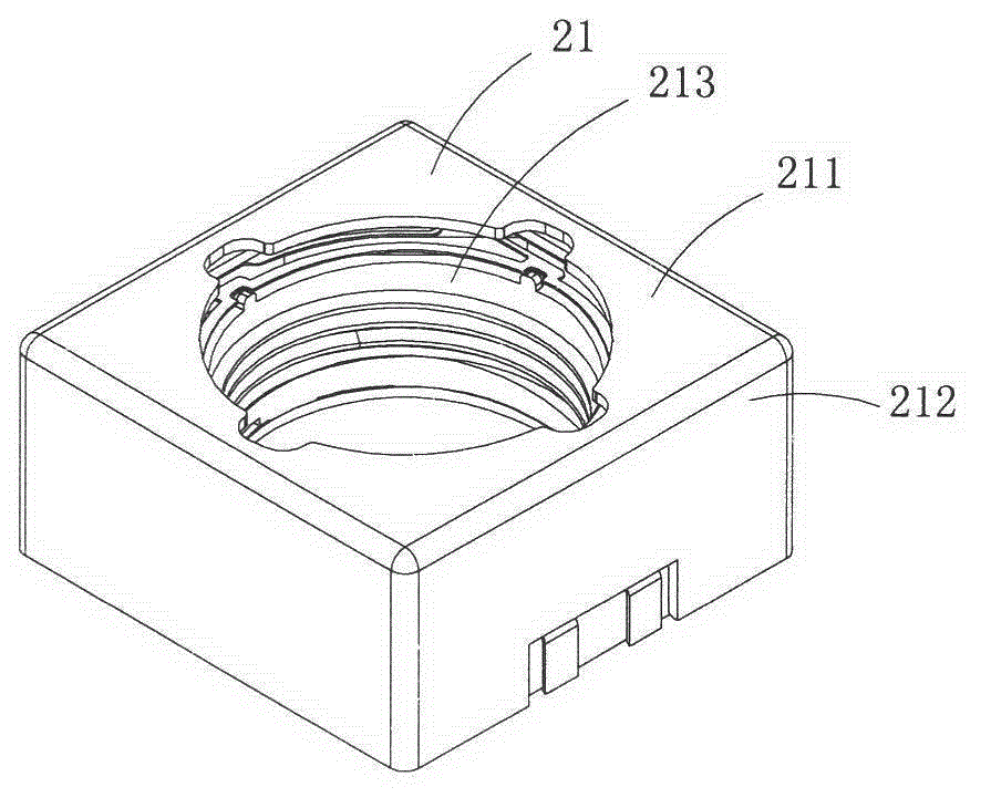
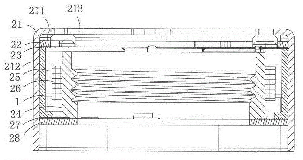
[0025] Figure 1 to Figure 3 Shows the first specific implementation of the micro drive motor of the present invention, wherein figure 1 It is a schematic diagram of a three-dimensional structure of the first structure of the micro drive motor of the present invention; figure 2 yes figure 1 A cutaway view of the micro drive motor shown; image 3 yes figure 1 An exploded view of the miniature drive motor shown.
[0026] Present embodiment is a kind of micro-drive motor for linearly driving micro-lenses, see Figure 1 to Figure 3 As shown, it includes a positioning bracket 1 , an upper cover 21 , an upper gasket 22 , an upper spring piece 23 , a carrier 24 , a magnet assembly 25 , a coil assembly 26 , a lower spring assembly 27 and a base 28 . The positioning bracket 1 is made of insulating plastic, and the upper cover 21 is made of magnetically conductive material.
[0027] The upper cover 21 includes a top wall 211 and a side ...
Embodiment 2
[0036] (Embodiment 2, miniature drive motor)
[0037] Figure 4 It is an exploded view of the second structure of the micro drive motor of the present invention, showing the second specific implementation of the micro drive motor of the present invention.
[0038] This embodiment is a micro drive motor made by the above-mentioned embodiment 1, which is basically the same as that of embodiment 4, except that the magnet assembly 25 includes four cuboid magnets 251, and each magnet 251 is adjacent to the upper cover correspondingly. One of the side walls 212 is set, that is, it is set in parallel with the corresponding one of the side walls 212; so in order to cooperate with this kind of magnet assembly, each support boss (12) in the positioning bracket 1 is located at two adjacent pressing edges ( 111), so that it is in the gap between two adjacent magnets 251.
Embodiment 3
[0039] (Embodiment 3, miniature drive motor)
[0040] Figure 5 and Figure 6 Shows the third embodiment of the micro drive motor of the present invention, wherein Figure 5 It is a cross-sectional view of the third structure of the micro drive motor of the present invention; Figure 6 yes Figure 5 A schematic diagram of a three-dimensional structure of the positioning bracket in the micro drive motor shown
[0041] This embodiment is basically the same as Embodiment 1, except that the base 28 is made of insulating plastic and has a central hole 281, and the plate-shaped body 11 of the positioning bracket 1 presses the outer edges 273 of the two elastic pieces 271. Connected and fixed on the insulating base 28.
PUM
 Abstract
Description
Claims
Application Information
 - R&D
- Intellectual Property
- Life Sciences
- Materials
- Tech Scout
- Unparalleled Data Quality
- Higher Quality Content
- 60% Fewer Hallucinations
Browse by: Latest US Patents, China's latest patents, Technical Efficacy Thesaurus, Application Domain, Technology Topic, Popular Technical Reports.
© 2025 PatSnap. All rights reserved.Legal|Privacy policy|Modern Slavery Act Transparency Statement|Sitemap|About US| Contact US: help@patsnap.com


