A micro drive motor

A micro-drive and motor technology, applied in the direction of electrical components, electromechanical devices, etc., can solve problems such as changes and affect the linear movement effect, and achieve the effect of simplifying the structure, improving the linear driving effect, and improving the production efficiency and yield.

Inactive Publication Date: 2015-10-21
深圳市光控数码光电有限公司
View PDF5 Cites 0 Cited by
  • Summary
  • Abstract
  • Description
  • Claims
  • Application Information

AI Technical Summary

Problems solved by technology

[0003] The traditional micro-drive motor generally includes an upper cover, an upper gasket, an upper spring piece, a lens carrier, a magnet assembly, a coil assembly, a lower gasket, a lower spring assembly and a base; the traditional upper cover is made of a magnetically conductive material, and the magnet The assembly is located under the top wall of the upper cover, and there is no magnetically conductive material under the magnet assembly, so most of the magnetic force lines of each magnet in the magnet assembly enter the top wall of the upper cover upward after passing through the coil assembly, and return to the magnet from the side wall of the upper cover , forming a closed magnetic circuit; thus, the magnetic force lines of each magnet near the top wall of the upper cover are relatively dense, while the magnetic force lines away from the top wall of the upper cover are relatively sparse, resulting in the coil assembly moving up and down with the carrier. The magnetic field at the place changes, affecting its linear movement effect

Method used


Image

  • A micro drive motor
  • A micro drive motor
  • A micro drive motor

Examples


Embodiment 1

[0016] (Example 1, micro drive motor)

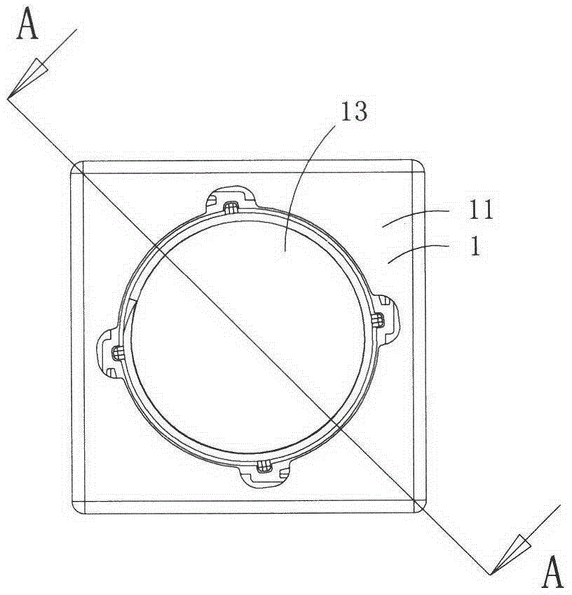
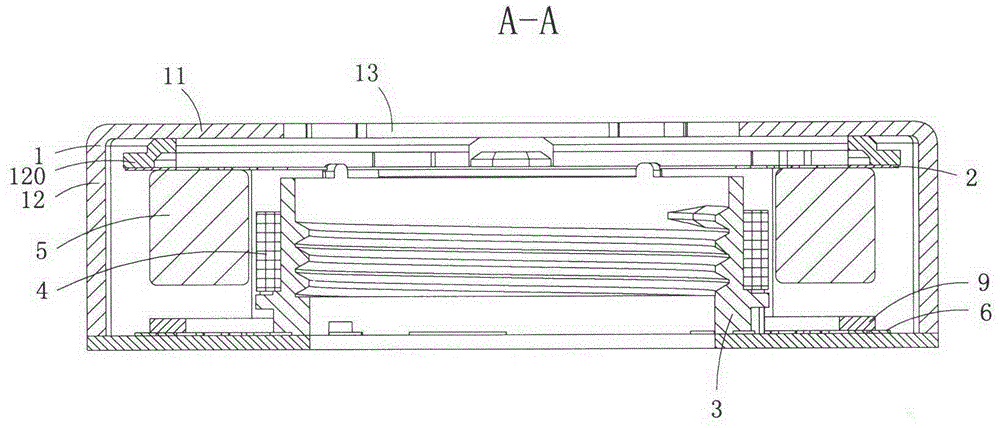
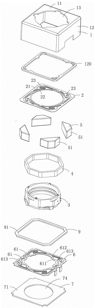
[0017] Figure 1 to Figure 3 The first specific embodiment of the micro-drive motor of the present invention is shown, in which, figure 1 It is a front view of the micro drive motor of the present invention; figure 2 Yes figure 1 A cross-sectional view of the micro drive motor shown along the line A-A; image 3 Yes figure 1 An exploded view of the micro drive motor shown;

[0018] This embodiment is a miniature drive motor that drives the lens assembly of a miniature camera, see Figure 1 to Figure 3 As shown, it includes an upper cover 1, an upper gasket 120, an upper spring sheet 2, a carrier 3, a coil assembly 4, a magnet assembly 5, a lower spring assembly 6, a base 7 and a lower gasket 9. In this embodiment, the upper cover 1, the upper gasket 120, the upper spring sheet 2, and the carrier 3 are all made of non-magnetic materials.

[0019] The upper cover 1 includes a top wall 11 and four side walls 12 connected to the top wall 11. The ...

Embodiment 2

[0029] (Example 2, micro drive motor)

[0030] Figure 4 It is an exploded view of the second structure of the micro-drive motor of the present invention, and shows the second specific embodiment of the micro-drive motor of the present invention.

[0031] This embodiment is basically the same as embodiment 1, but the difference is: the lower gasket 9 in this embodiment also includes support plates 92 protruding upward from the center of each side of the pressure plate, and each support plate 92 is located on two adjacent magnets. In the gap 51, the top surface abuts on the bottom surface of the outer ring 21 of the upper spring leaf.

Embodiment 3

[0032] (Example 3, micro drive motor)

[0033] This embodiment is basically the same as embodiment 1, except that: the upper cover 1 is made of a magnetically conductive material; a magnetic path is also formed between a side of the magnet assembly 5 close to the coil assembly 4 and the top wall of the upper cover. This structure can effectively provide the use efficiency of the magnetic field of the magnet assembly, and can provide a more constant magnetic field for the coil assembly when the coil assembly moves with the carrier, thereby effectively improving the linear driving effect.


PUM


Abstract

The invention discloses a miniature drive motor which comprises an upper cover, an upper gasket, an upper spring leaf, a carrier, a coil component, a magnetic component, a lower spring component, a lower gasket and a base. The base comprises magnetic body of a basically flat plate shape. The base is provided with a central hole. The peripheral edges of the base is fixed on the side wall of the upper cover and the bottom surface. The side, close to the coil component, of the magnetic component and the base form a magnetic passage for allowing penetration of the coil component. The lower gasket comprises a pressing plate of a basically rectangular frame shape. The outer edge of the lower spring leaf is pressed to the base magnetic body. By the modified base position, the base is matched with the upper cover for use, and accordingly structure of traditional miniature drive motors is simplified greatly, and production efficiency and yield are improved effectively.

Description

Technical field [0001] The invention belongs to the technical field of micro motor structure design, and specifically relates to a micro drive motor. Background technique [0002] Micro camera devices have been widely used in mobile phones and notebook computers, and the micro drive motors (also called lens drive motors) have become smaller and smaller. [0003] The traditional micro drive motor generally includes an upper cover, an upper spacer, an upper spring sheet, a lens carrier, a magnet assembly, a coil assembly, a lower spacer, a lower spring sheet assembly and a base; the traditional upper cover is made of magnetically conductive materials, and the magnet The component is located under the top wall of the upper cover, and there is no magnetic material under the magnet component, so most of the magnetic field lines of each magnet in the magnet component enter the top wall of the upper cover after passing through the coil component, and return to the magnet from the side wal...

Claims


Application Information

Patent Timeline
Patent Type & Authority Patents(China)
IPC IPC(8): H02K33/18
Inventor 夏太红彭全斌
Owner 深圳市光控数码光电有限公司
Why Eureka
Try Eureka