Improved micro drive motor

A micro-drive motor, an improved technology, applied in the direction of electrical components, electromechanical devices, etc., can solve the problem of inability to guarantee the bonding strength, the difficulty of accurately ensuring the distance between the outer ring of the spring leaf and the outer edge of the lower spring leaf, and the difficulty of ensuring the upper spring leaf and the lower spring leaf. and other problems to achieve the effect of improving the linear drive effect

Inactive Publication Date: 2015-10-21
深圳市光控数码光电有限公司
View PDF4 Cites 0 Cited by
  • Summary
  • Abstract
  • Description
  • Claims
  • Application Information

AI Technical Summary

Problems solved by technology

[0005] The difficulty brought about by this method is: in order to ensure the consistency of elastic deformation, it is necessary to strictly control the distance between the outer ring of the upper spring leaf and the outer edge of the lower spring leaf, and the distance between the inner ring of the upper spring leaf and the inner edge of the lower spring leaf; Since the inner ring of the upper spring is fixed on the top of the carrier, and the inner edge of the lower spring is fixed on the bottom of the carrier, both are fixed on the same part, so it is only necessary to ensure the processing accuracy of the carrier, that is, the inner ring of the upper spring and the inner ring of the upper spring can be easily controlled. The spacing between the inner edges of the lower shrapnel; however, the outer ring of the upper spring leaf and the outer edge of the lower shrapnel are respectively fixed on different parts, and the thicker part between the two is the magnet assembly, but the magnet assembly itself The processing accuracy is low and the error is large, so it cannot be used to locate the distance between the two; in addition, in traditional products, the outer ring of the upper spring and the upper gasket are fixed on the upper cover, and the installation position is limited by the accuracy and fixing method of the upper cover; The outer edge of the lower shrapnel is crimped and fixed on the base by the lower gasket, and its installation position is limited by the accuracy of the base and the fixing method; finally, the upper cover is glued and fixed on the base, so it is difficult to accurately ensure the distance between the outer ring of the spring leaf and the outer edge of the lower shrapnel That is, it is difficult to ensure that the elastic deformation produced by the upper spring and the lower spring just offsets the gravity produced by the carrier and the lens, thus affecting the linear drive effect
[0006] In addition, in traditional products, each magnet in the magnet assembly is fixed by glueing its outer wall adjacent to the side wall of the upper cover to the side wall of the upper cover. The bonding effect cannot be known through direct observation, so the bonding cannot be guaranteed. As a result, in the drop test, due to the severe impact force, once the bonding strength of the magnet is slightly poor, it will loosen or even fall off from the side wall of the upper cover, resulting in defective products, so its structure also needs improvement. place

Method used


Image

  • Improved micro drive motor
  • Improved micro drive motor
  • Improved micro drive motor

Examples


Embodiment 1

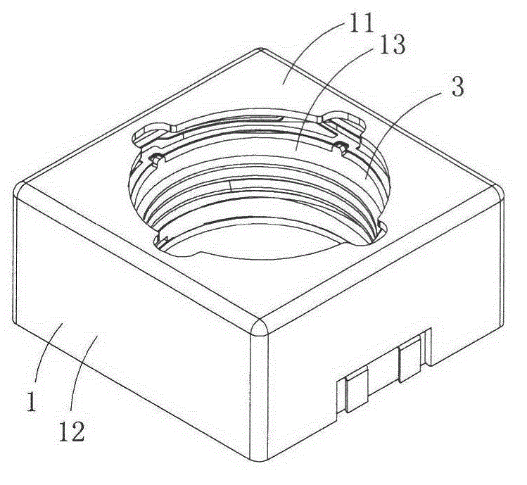
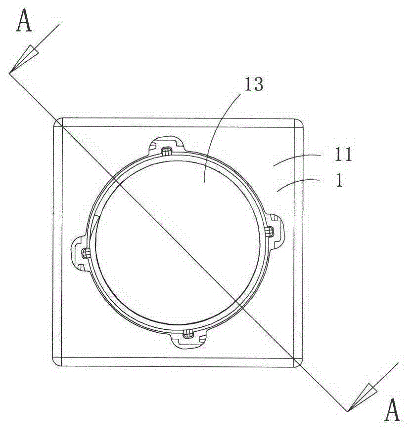
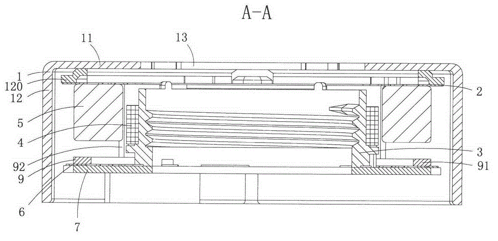
[0022] Figure 1 to Figure 4 A first embodiment of the invention is shown in which, figure 1 It is a schematic diagram of a three-dimensional structure of the present invention; figure 2 yes figure 1 A front view of the improved miniature drive motor shown; image 3 yes figure 2 The sectional view of the improved miniature drive motor shown along the A-A line; Figure 4 yes figure 1 An exploded view of the modified micro-drive motor shown.

[0023] Present embodiment is a kind of improved miniature driving motor of driving miniature camera lens assembly, see Figure 1 to Figure 4 As shown, it includes an upper cover 1, an upper gasket 120, an upper spring piece 2, a carrier 3, a coil assembly 4, a magnet assembly 5, a lower spring assembly 6, a magnetic guide 7 and a lower gasket 9; the upper gasket 120 , the upper spring piece 2, the carrier 3, and the lower gasket 9 are all made of non-magnetic materials;

[0024] The upper cover 1 includes a top wall 11 and four s...

Embodiment 2

[0039] This embodiment is basically the same as Embodiment 1, except that: the upper cover 1 is made of magnetically permeable material; a magnetic path is also formed between a side of the magnet assembly 5 close to the coil assembly 4 and the top wall of the upper cover. This structure can effectively improve the utilization efficiency of the magnetic field of the magnet assembly, and can provide a more constant magnetic field for the coil assembly when the coil assembly moves with the carrier, thereby effectively improving the linear driving effect.

Embodiment 3

[0041] This embodiment is basically the same as Embodiment 1, except that: the two ends of each support boss 12 along the circumferential direction of the coil assembly 26 abut against two adjacent magnets 251 . This structure can limit the position of each magnet in the circumferential direction of the coil assembly, increase the impact resistance of the magnet assembly, and is beneficial to improve the passing rate of the drop test.


PUM


Abstract

The invention discloses a modified miniature driving motor which comprises an upper cover, an upper gasket, an upper spring piece, a carrier, a coil component, a magnet component, a lower spring component and a lower gasket. The magnet component comprises four magnets in shapes of trapezoid basically, a side face, close to the coil component, of each magnet is an N pole or S pole, the side face, far away from the coil component, of each magnet is an S pole or N pole, the magnets are arranged at an inner corner formed by clamping of two adjacent side walls of the upper cover, gaps are reserved between two adjacent magnets, the lower gasket comprises a press plate in a shape of rectangular frame basically and supporting plates protruding upwards from the press plate, each supporting plate is positioned in the gaps between two adjacent magnets, and the top surface of each supporting plate is abutted on an outer ring of the upper spring piece. The modified miniature driving motor can effectively guarantee linear driving effect.

Description

technical field [0001] The invention belongs to the technical field of micro-motor structure design, and in particular relates to an improved micro-drive motor. Background technique [0002] Micro camera devices have been widely used in mobile phones and notebook computers, and the micro drive motors (also called lens drive motors) therein are getting smaller and smaller. [0003] Traditional micro-drive motors generally include an upper cover, an upper gasket, an upper spring sheet, a lens carrier, a magnet assembly, a coil assembly, a lower gasket, a lower spring sheet assembly, and a base; the traditional upper cover is made of a magnetically conductive material, and the magnet The assembly is located under the top wall of the upper cover, and there is no magnetically conductive material under the magnet assembly, so most of the magnetic force lines of each magnet in the magnet assembly enter the top wall of the upper cover upward after passing through the coil assembly, ...

Claims


Application Information

Patent Timeline
Patent Type & Authority Patents(China)
IPC IPC(8): H02K33/18H02K33/02
Inventor 夏太红彭全斌
Owner 深圳市光控数码光电有限公司
Why Eureka
Try Eureka