Ultrasonic flow rate measurement unit

A flow measurement and ultrasonic technology, applied in the field of ultrasonic flow measurement unit, can solve the problems of high price and troublesome installation

Inactive Publication Date: 2013-03-27
PANASONIC CORP
View PDF4 Cites 4 Cited by
  • Summary
  • Abstract
  • Description
  • Claims
  • Application Information

AI Technical Summary

Problems solved by technology

Therefore, there are problems that the vibration transmission suppressor 55 for holding the support portion of the ultrasonic vibrators 51 and 52 is expensive and the installation of the ultrasonic vibrators 51 and 52 is troublesome.

Method used


Image

  • Ultrasonic flow rate measurement unit
  • Ultrasonic flow rate measurement unit
  • Ultrasonic flow rate measurement unit

Examples


Embodiment approach 1

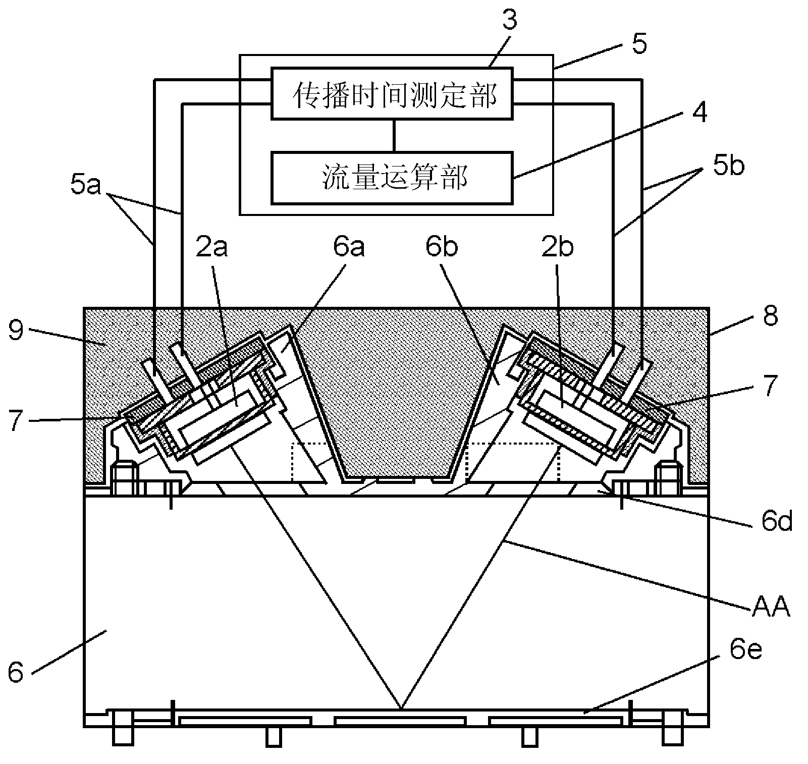
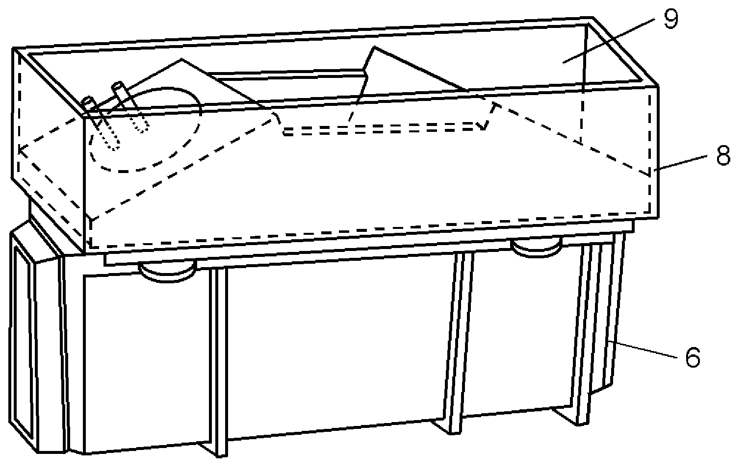
[0015] Below, use Figure 1A and Figure 1B The ultrasonic flow rate measurement unit according to Embodiment 1 of the present invention will be described. Figure 1A It is a cross-sectional view of the ultrasonic flow rate measurement unit according to Embodiment 1 of the present invention. Figure 1B It is a perspective view of the ultrasonic flow rate measurement unit of this embodiment.

[0016] like Figure 1A and Figure 1B As shown, the ultrasonic flow measurement unit is composed of at least a measurement channel 6, a pair of ultrasonic vibrators 2a and 2b accommodated in a housing 8, a measurement circuit board 5, and a vibration damping member 9 made of a vibration damping material. The measurement circuit board 5 includes a propagation time measurement unit 3 connected to a pair of ultrasonic transducers 2a, 2b via lead wires 5a, 5b, and a flow calculation unit 4. In the case 8, a vibration damping member 9 is filled to cover the pair of ultrasonic vibrators 2a...

Embodiment approach 2

[0025] Below, use Figure 2A and Figure 2B An ultrasonic flow rate measurement unit according to Embodiment 2 of the present invention will be described. Figure 2A It is a cross-sectional view of the ultrasonic flow rate measurement unit according to Embodiment 2 of the present invention. Figure 2B It is a perspective view of the ultrasonic flow rate measurement unit of this embodiment.

[0026] like Figure 2A and Figure 2B As shown, the difference between the ultrasonic flow measurement unit of the present embodiment and the first embodiment is that the measurement circuit board 11 is arranged between the pair of ultrasonic vibrators 2a, 2b and stored in the housing 8, and the vibration-damping member 9 is used to cover the measurement unit. A circuit board 11 and a pair of ultrasonic vibrators 2a, 2b. The other structures and functions are basically the same as those in Embodiment 1, and therefore descriptions thereof are omitted.

[0027] That is, if Figure 2A ...


PUM


Abstract

Disclosed is an ultrasonic flow rate measurement unit comprising: a measurement flow path provided with a case that houses a pair of ultrasonic oscillators and through which passes a fluid to be measured; the pair of ultrasonic oscillators disposed in the measurement flow path; a propagation time measurement unit that measures the propagation time for transmission and reception between the ultrasonic oscillators; a measurement circuit substrate formed by a flow rate calculation unit that arithmetically calculates the flow rate of the fluid to be measured from the propagation time measured by the propagation time measurement unit; and a vibration absorbing material that is filled into a case that covers the pair of ultrasonic oscillators.

Description

technical field [0001] The present invention relates to an ultrasonic flow measuring unit used in an ultrasonic flow measuring device, etc. The ultrasonic flow measuring device uses a pair of ultrasonic vibrators capable of transmitting and receiving to measure the propagation time of ultrasonic signals to measure fluids to be measured such as air and gas traffic. Background technique [0002] Conventional ultrasonic flow measuring devices have, for example, image 3 structure shown. image 3 It is a block diagram of a conventional ultrasonic flow measurement device. [0003] like image 3 As shown, the conventional ultrasonic flow measurement device includes: a measurement flow path 50 through which the fluid to be measured flows; at least a pair of ultrasonic vibrators 51, 52 arranged opposite to the measurement flow path 50 to transmit and receive ultrasonic waves. the measurement control unit 53 which measures the propagation time of the ultrasonic waves between the ult...

Claims


Application Information

Patent Timeline
Patent Type & Authority Applications(China)
IPC IPC(8): G01F1/66
CPCG01F1/66G01F1/662
Inventor 渡边葵藤井裕史中林裕治佐藤真人后藤寻一
Owner PANASONIC CORP
Why Eureka
Try Eureka