
Fischer-Tropsch synthesis device starting method

A Fischer-Tropsch synthesis and reaction technology, applied in chemical instruments and methods, chemical/physical processes, etc., to achieve the effects of smooth start-up, simple and practical operation, and improved operation stability

Active Publication Date: 2015-03-18
CHINA PETROLEUM & CHEM CORP +1
View PDF5 Cites 0 Cited by
  • Summary
  • Abstract
  • Description
  • Claims
  • Application Information

AI Technical Summary

Problems solved by technology

[0006] The purpose of the present invention is to provide a Fischer-Tropsch synthesis device start-up method on the basis of the prior art, to solve the problem of over-temperature risk in the initial start-up of the Fischer-Tropsch synthesis device, and to improve the operation stability of the device in the initial start-up period

Method used


Image

  • Fischer-Tropsch synthesis device starting method

Examples


Embodiment 1

[0025] After the cobalt-based fixed-bed Fischer-Tropsch synthesis catalyst is loaded into the reactor, the catalyst is first reduced in a pure hydrogen atmosphere. The reduction conditions are: temperature 400°C, pressure 0.5MPa, gas space velocity 500h -1 , Reduction time 24h.

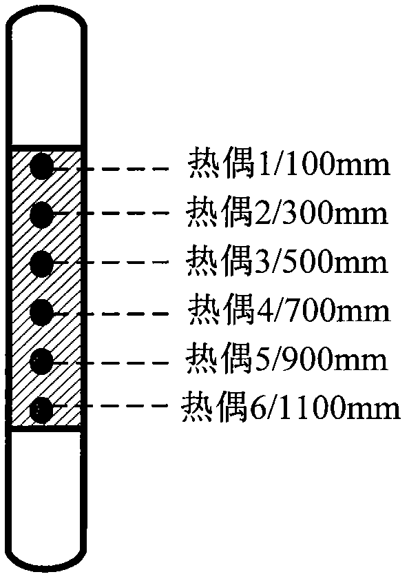
[0026] The reduced catalyst was cooled to 150°C in a hydrogen atmosphere, and synthesis gas was introduced into the reactor (gas space velocity 500h -1 , hydrogen / carbon monoxide molar ratio 2.0), and raise the system pressure to 2.5MPa. After the pressure rises to the required value, start the cycle compressor to establish a gas cycle (control cycle ratio is 8.0), and increase the temperature at a rate of 2°C / h Raise the average temperature of the bed to 190°C and keep the temperature at 190°C for 24 hours. See Table 1 for the bed temperature distribution at this stage.

[0027] After the catalyst was kept at 190°C for 24 hours, the average temperature of the bed was raised to 200°C at a rate of 1°C...

Embodiment 2

[0036] After loading the cobalt-based fixed-bed Fischer-Tropsch synthesis catalyst into the reactor, the catalyst is first reduced in a pure hydrogen atmosphere, and the reduction conditions are the same as in Example 1.

[0037] The reduced catalyst was cooled to 150°C in a hydrogen atmosphere, and synthesis gas was introduced into the reactor (gas space velocity 750h -1 , hydrogen / carbon monoxide molar ratio 2.0), and raise the system pressure to 2.5MPa. After the pressure rises to the required value, start the cycle compressor to establish a gas cycle (control cycle ratio is 8.5), and increase the temperature at a rate of 2°C / h Raise the average temperature of the bed to 190°C and keep the temperature at 190°C for 24 hours. See Table 3 for the bed temperature distribution at this stage.

[0038] After the catalyst was kept at 190°C for 24 hours, the average temperature of the bed was raised to 205°C at a rate of 1°C / h, and kept at 205°C for 40 hours. See Table 3 for the bed...


PUM


Abstract

The invention discloses a Fischer-Tropsch synthesis device starting method. The Fischer-Tropsch synthesis device starting method comprises the following step that 1, a Fischer-Tropsch synthesis catalyst is reduced by reduction gas at a temperature of 300 to 600 DEG C; 2, a Fischer-Tropsch synthesis reaction process is carried out under the condition of an axial temperature difference delta T1 of a catalyst bed; 3, a Fischer-Tropsch synthesis reaction process is carried out under the condition of an axial temperature difference delta T2 of the catalyst bed; and 4, a Fischer-Tropsch synthesis reaction process is carried out under the condition of an axial temperature difference delta T3 of the catalyst bed so that a liquid hydrocarbon is produced, wherein the axial temperature difference delta T1 is more than 0DEG C and less than 1 / 2 of the axial temperature difference delta T2; and the axial temperature difference delta T2 is more than 1 / 3 the axial temperature difference delta T3 and less than 2 / 3 of the axial temperature difference delta T3. The Fischer-Tropsch synthesis device starting method can solve the problem that in Fischer-Tropsch synthesis device starting, a temperature is over the standard temperature easily, and can improve starting smoothness.

Description

technical field [0001] The invention relates to a start-up method of a Fischer-Tropsch synthesis device. Background technique [0002] Fischer-Tropsch synthesis is a strong exothermic reaction. In the early stage of plant operation, due to the high initial activity of the catalyst, it is very easy to cause local hot spots in the catalyst bed. If the hot spots deteriorate, it will cause the catalyst bed to overheat, resulting in a decline in catalyst performance. Even scrapped. Therefore, it is very important to realize the smooth start-up of the Fischer-Tropsch synthesis unit for the efficient operation of the unit. [0003] CN1167650C discloses a production method for synthesizing hydrocarbons from synthesis gas. The method is to use dilute synthesis gas containing nitrogen to synthesize hydrocarbons under the action of a catalyst. In the method, the concentration of reactants is reduced by adding nitrogen into the synthesis gas, thereby reducing the heat release per uni...

Claims


Application Information

Patent Timeline
Patent Type & Authority Patents(China)
IPC IPC(8): B01J8/02
Inventor 吴昊胡志海聂红徐润李猛侯朝鹏孙霞
Owner CHINA PETROLEUM & CHEM CORP
Learn More